Audi Q7: Control Module and Hydraulic Unit
Overview - Control Module and Hydraulic Unit
 Note
Note
- If the ABS Control Module -J104- is faulty it can be replaced separately.
- If the ABS Hydraulic Unit -N55- is faulty it must be replaced together with the ABS Control Module -J104-.
Control Module and Hydraulic Unit
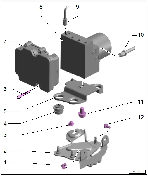
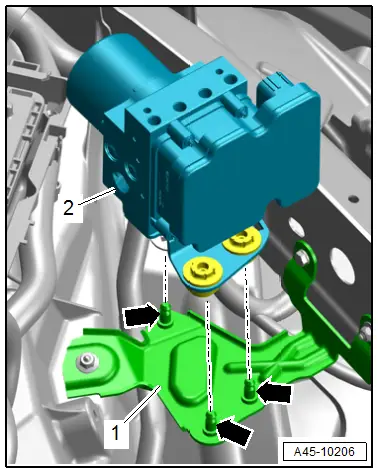
1 - Nut
- 3.8 Nm
2 - Bracket
3 - Nut
- 3.8 Nm
4 - Rubber Bushing
5 - Mounting Bracket
6 - Bolt
- Tighten in two steps alternating from side to side.
- Step 1: 1 to 1.5 Nm (to install the seal)
- Step 2: 2.5 Nm
7 - ABS Control Module -J104-
 Note
Note
- If the ABS Control Module -J104- is faulty it can be replaced separately.
- If the ABS Hydraulic Unit -N55- is faulty it must be replaced together with the ABS Control Module -J104-.
- Refer to → Chapter "ABS Control Module -J104-/ABS Hydraulic Unit -N55-, Removing and Installing"
- Can be replaced separately if faulty.
- Refer to → Chapter "Control Module, Separating from Hydraulic Unit"
- Refer to → Chapter "Control Module, Installing on Hydraulic Unit"
8 - ABS Hydraulic Unit -N55-
 Note
Note
- If the ABS Control Module -J104- is faulty it can be replaced separately.
- If the ABS Hydraulic Unit -N55- is faulty it must be replaced together with the ABS Control Module -J104-.
- Refer to → Chapter "ABS Control Module -J104-/ABS Hydraulic Unit -N55-, Removing and Installing"
9 - Brake Line
- 14 Nm
- 5.25 mm diameter and union bolt with M12x1 thread
- To the brake caliper
10 - Brake Line
- 14 Nm
- From brake master cylinder to the hydraulic unit
- 6 mm diameter and union bolt with M12x1 thread
11 - Bolt
- 25 Nm
12 - Bolt
- 3.8 Nm
ABS Control Module -J104-
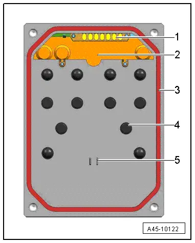
1 - Pressure Sensor Contact
- Do not touch the contact
- The illustration depends on the model
2 - Pressure Sensor
- Must not be changed or damaged
- Cannot be replaced
- The illustration depends on the model
3 - Seal
- Do not remove or lift
- Cannot be replaced separately
4 - Valve Body
- Must not be damaged
- Do not use any tools
5 - Pump Motor Contact
- Must not be damaged
ABS Control Module -J104-/ABS Hydraulic Unit -N55-, Removing and Installing
Special tools and workshop equipment required
- Vehicle Diagnostic Tester
- Torque Wrench 1331 5-50Nm -VAG1331-
- Brake Pedal Actuator -VAG1869/2-.
- er bottle from the Brake Charger/er Unit -VAS5234-
- M10 plug -item 1- or M12 -item 2- from the Assembly Part Set -5Q0 698 311-
- Safety Gloves
 Note
Note
- If the ABS Control Module -J104- is faulty it can be replaced separately.
- If the ABS Hydraulic Unit -N55- is faulty it must be replaced together with the ABS Control Module -J104-.
Removing
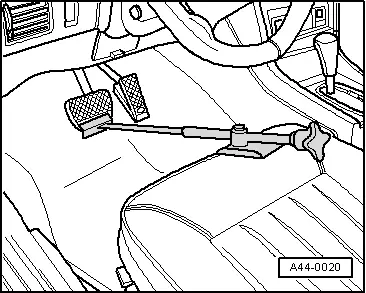
- Insert the Brake Pedal Actuator -VAG1869/2- between the brake pedal and driver seat. Press the brake pedal down at least 60 mm.
 Note
Note
By doing this, the valves in the brake master cylinder are closed and the brake fluid reservoir does not run empty.
 WARNING
Risk of skin irritation.
To prevent skin contact with brake fluid, wear chemical resistant safety gloves.
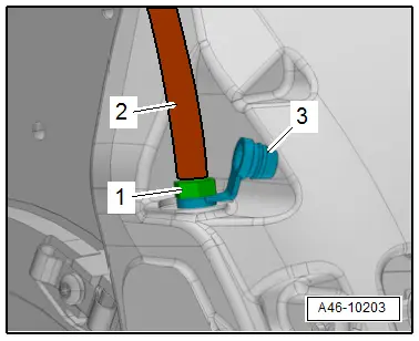
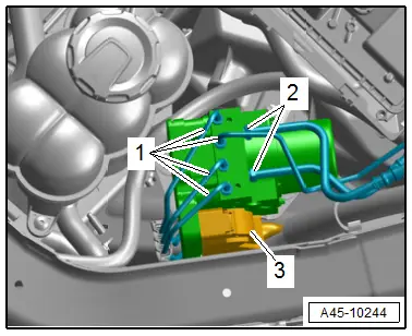
- Remove the protective cap -3- from the bleed screw -1- on the left front caliper.
- Connect the bleeder bottle hose -2- as shown.
- Open the bleed screw to reduce the pressure in the brake system.
- Close the bleed screw and remove the bleeder bottle.
- Repeat the procedure on the left rear brake caliper.
 Note
Note
Do not remove the Brake Pedal Actuator -VAG1869/2-.
Vehicles with 3.0L TFSI engine
- Remove the air filter upper section. Refer to → Rep. Gr.24; Air Filter; Air Filter Housing, Removing and Installing.
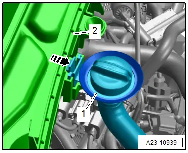
- Release the catch in direction of -arrow-, free up the oil filler tube -1- on the air filter lower section -2- and push to the side.
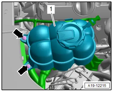
- Remove the bolts -arrows- and push the coolant expansion tank -1- to the right side of the vehicle.
Continuation for All Vehicles
 Note
Note
To protect against escaping brake fluid, place enough lint-free cloths in the area below the hydraulic control module.
- Mark the brake lines for reinstallation.
- Remove the brake lines -1 and 2- from the ABS Hydraulic Unit -N55-.
 Caution
Risk of damaging the brake lines.
Do not change the bending shape.
- Immediately seal brake lines and threaded holes with clean plug from the Assembly Part Set -5Q0 698 311-.
- Release the connector -3- and disconnect from the control module.
 Note
Note
Make sure that no brake fluid enters the control module connector housing.
- Free up the wire.
 Caution
Risk of damaging the brake lines.
Do not change the bending shape.
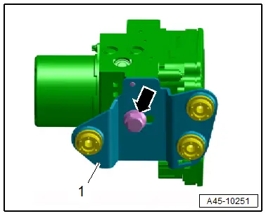
- Remove the hydraulic control unit -2- carefully from the pins -arrows- on the bracket -1-.

Remove the bolt -arrow- and the bracket -1-.
 Note
Note
- The ABS Control Module -J104- can be replaced separately if faulty. Refer to → Chapter "Control Module, Separating from Hydraulic Unit".
- The ABS Hydraulic Unit -N55- must be replaced together with the ABS Control Module -J104- if faulty.
Installing
Install in reverse order of removal and note the following:
- Carefully press the hydraulic control unit -2- in the pins -arrows- on the bracket -1-.
- The hydraulic control module must rest in all pins.
- Insert the brake lines -1 and 2- in the ABS Hydraulic Unit -N55- install the union bolts by hand and tighten.
- Connect the connector -3-.
- After securing the brake lines to the hydraulic unit, perform output diagnostic test mode. Refer to Vehicle Diagnostic Tester.

 Note
Note
It can be determined in output diagnostic test mode, whether the line connections were interchanged.
- Remove the Brake Pedal Actuator -VAG1869/2-.
- Bleed the brake system. Refer to → Chapter "Hydraulic System, Bleeding".
- If the ABS Control Module -J104-/ABS Hydraulic Unit -N55- is being replaced, select the "Replace" function for the ABS Control Module -J104-/ABS Hydraulic Unit -N55-. Refer to Vehicle Diagnostic Tester, Guided Functions.
 WARNING
Risk of accident!
Make sure the brakes are working correctly before driving the vehicle for the first time.
Tightening Specifications
- Refer to → Chapter "Overview - Control Module and Hydraulic Unit"

