Audi Q7: Sensors
Overview - Front Axle Speed Sensor
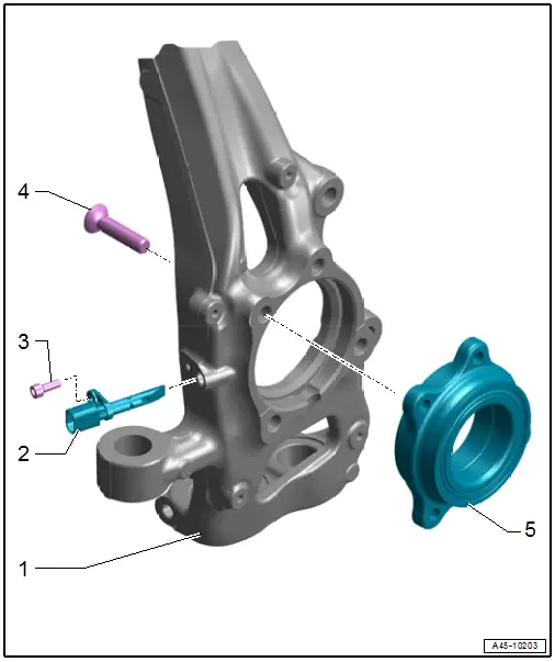
1 - Wheel Bearing Housing
- Clean the inner surface of the hole before inserting the speed sensor.
2 - Front Speed Sensor
- Right Front ABS Wheel Speed Sensor -G45-
- Left Front ABS Wheel Speed Sensor -G47-
- Refer to → Chapter "Right and Left Front ABS Wheel Speed Sensor - G45-/-G47-, Removing and Installing"
- Coat the speed sensor all around with Grease -G 000 650- before inserting.
3 - Bolt
- 9 Nm
4 - Bolt
- Tightening specification. Refer to → Suspension, Wheels, Steering; Rep. Gr.40; Wheel Bearing; Overview - Wheel Bearing.
5 - Wheel Bearing
- With integrated ABS sensor ring
Overview - Rear Axle Speed Sensor
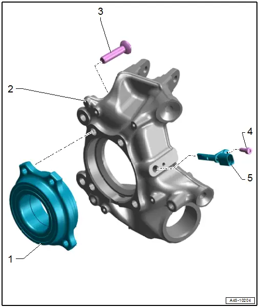
1 - Wheel Bearing
- With integrated ABS sensor ring
2 - Wheel Bearing Housing
- Clean the inner surface of the hole before inserting the speed sensor.
3 - Bolt
- Tightening specification. Refer to → Suspension, Wheels, Steering; Rep. Gr.42; Wheel Bearing and Trailing Arm; Overview - Wheel Bearing.
4 - Bolt
- 9 Nm
5 - Rear Speed Sensor
- Right Rear ABS Wheel Speed Sensor -G44-
- Left Rear ABS Wheel Speed Sensor -G46-
- Refer to → Chapter "Right and Left Rear ABS Wheel Speed Sensor - G44-/-G46-, Removing and Installing"
- Coat the speed sensor all around with Grease -G 000 650- before inserting.
Brake Lamp Switch, Removing and Installing
 Note
Note
Component location. Refer to → Chapter "Overview - Control Module and Hydraulic Unit".
Special tools and workshop equipment required
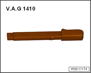
- Torque Wrench 1410 -VAG1410-
Removing
- Remove the plenum chamber cover. Refer to → Body Exterior; Rep. Gr.50; Bulkhead; Plenum Chamber Cover, Removing and Installing.
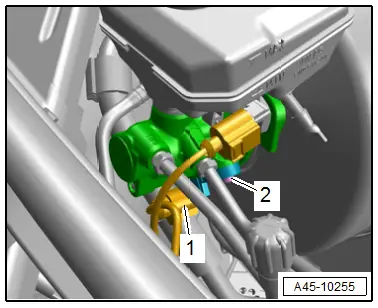
- Disconnect the connector -1-.
- Remove the bolt -2- and remove the Brake Lamp Switch -F- from the brake master cylinder.
Installing
Install in reverse order of removal and note the following:
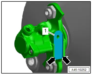
- Clean the contact surface -1- for the Brake Lamp Switch -F-.
- The brake lamp switch must be between the two edges -arrows- of the brake master cylinder.
- Install the plenum chamber cover. Refer to → Body Exterior; Rep. Gr.50; Bulkhead; Plenum Chamber Cover, Removing and Installing.
Tightening Specifications
- Refer to -item 17-
Right and Left Front ABS Wheel Speed Sensor - G45-/-G47-, Removing and Installing
Special tools and workshop equipment required
- Torque Wrench 1410 -VAG1410-
- Lubricant -G 000 650-. Refer to the Parts Catalog.
Removing
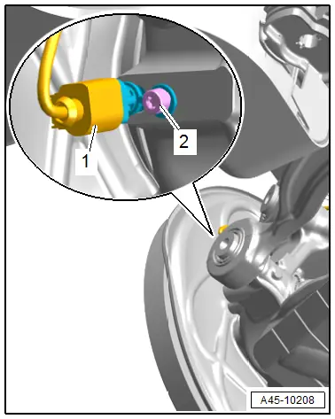
- Disconnect the connector -2-.
- Remove the bolt -1- and remove the speed sensor from the wheel bearing housing.
Installing
Install in reverse order of removal and note the following:
- Before inserting the speed sensor, clean the inner surface of the hole and coat the speed sensor all-round with Grease -G 000 650-.
Tightening Specifications
- Refer to → Chapter "Overview - Front Axle Speed Sensor"
Right and Left Rear ABS Wheel Speed Sensor - G44-/-G46-, Removing and Installing
Special tools and workshop equipment required
- Torque Wrench 1410 -VAG1410-
- Lubricant -G 000 650-. Refer to the Parts Catalog.
Removing
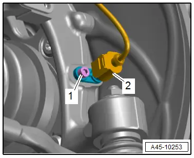
- Disconnect the connector -1-.
- Remove the bolt -2- and remove the speed sensor from the wheel bearing housing.
Installing
Install in reverse order of removal and note the following:
- Before inserting the speed sensor, clean the inner surface of the hole and coat the speed sensor all-round with Grease -G 000 650-.
Tightening Specifications
- Refer to → Chapter "Overview - Rear Axle Speed Sensor"
Special Tools
Special tools and workshop equipment required
- Torque Wrench 1331 5-50Nm -VAG1331-
- Torque Wrench 1410 -VAG1410-
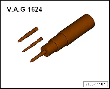
- Torque Screwdriver -VAG1624-
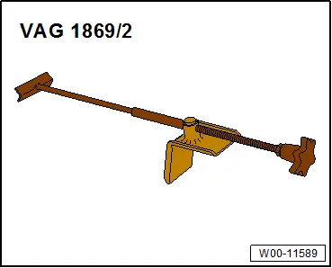
- Brake Pedal Actuator -VAG1869/2-.
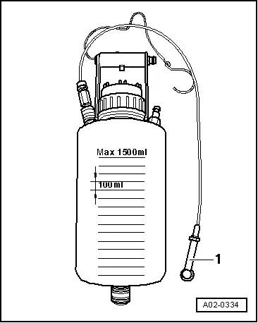
- Bleeder bottle from the Brake Charger/Bleeder Unit -VAS5234-
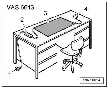
- ESD Work Surface -VAS6613-
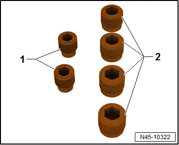
- M10 plug -item 1- or M12 -item 2- from the Assembly Part Set -5Q0 698 311-
- Safety Gloves
- Vehicle Diagnostic Tester
- Torx insert T25