Audi Q7: Coolant Pump/Coolant Thermostat
Overview - Coolant Pump/Coolant Thermostat
Coolant Pump/Coolant Thermostat
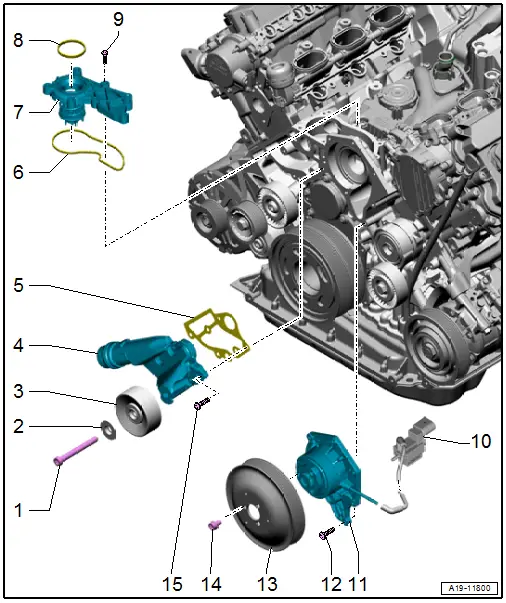
1 - Bolt
- Tightening specification. Refer to -item 9-
- Not available separately, one unit with -3-
2 - Washer
- Not available separately, one unit with -3-
3 - Idler Roller
- For the ribbed belt
- One unit with -1 and 2-
4 - Connection
- For coolant hose
5 - Seal
- Replace after removing
6 - Seal
- Replace after removing
7 - Coolant Thermostat
- Removing and installing. Refer to → Chapter "Coolant Thermostat, Removing and Installing".
- Starts to open: at approximately 87 ºC (188.6 ºF)
- Stops at: approximately 102 ℃ (215.6 ºF)
- Opening lift minimum 8 mm
8 - Seal
- Replace after removing
9 - Bolt
- 9 Nm
10 - Cylinder Head Coolant Valve -N489-
11 - Coolant Pump
- With seal
- Removing and installing. Refer to → Chapter "Coolant Pump, Removing and Installing".
12 - Bolt
- 9 Nm
13 - Ribbed Belt Pulley
- For the coolant pump
14 - Bolt
- 20 Nm
15 - Bolt
- 9 Nm
Overview - Electric Coolant Pump
Coolant Recirculation Pump -V50-, Transmission Fluid Cooling Valve -N509-
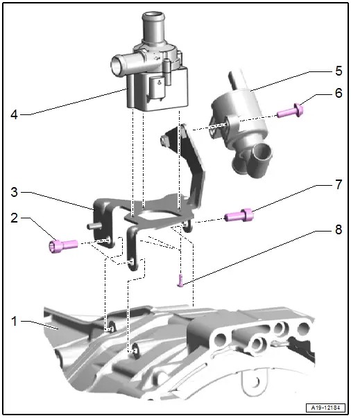
1 - Transmission
2 - Bolt
- 20 Nm
3 - Bracket
4 - Coolant Recirculation Pump -V50-
- Removing and installing. Refer to → Chapter "Coolant Recirculation Pump -V50-, Removing and Installing".
5 - Transmission Fluid Cooling Valve -N509-
- Removing and installing. Refer to → Chapter "Coolant Valves, Removing and Installing".
6 - Bolt
- 8 Nm
7 - Bolt
- 20 Nm
8 - Bolt
- 1.5 Nm
Charge Air Cooling Pump -V188-
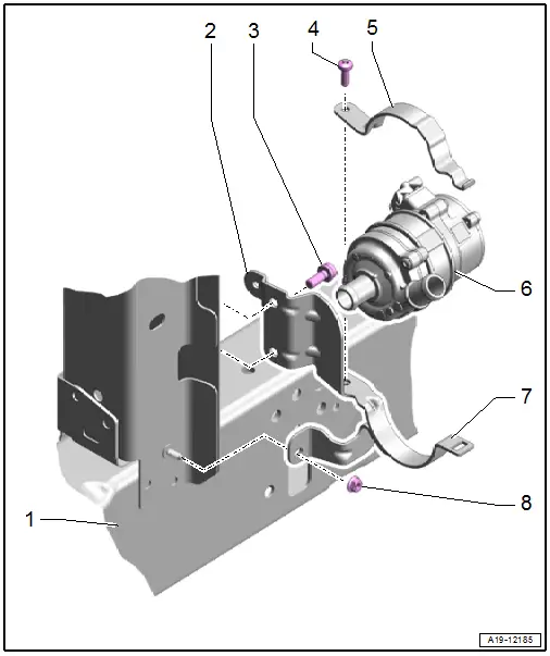
1 - Left Longitudinal Member
2 - Bracket
- For the Charge Air Cooling Pump -V188-
3 - Bolt
- 20 Nm
4 - Bolt
- 8 Nm
5 - Upper Retaining Bracket
6 - Charge Air Cooling Pump -V188-
- Removing and installing. Refer to → Chapter "Charge Air Cooling Pump -V188-, Removing and Installing".
7 - Lower Retaining Bracket
8 - Nut
- 5 Nm
Overview - Engine Coolant Temperature Sensor
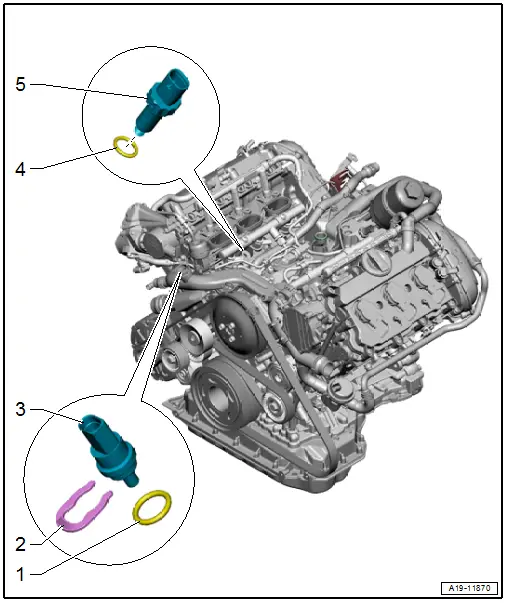
1 - O-Ring
- Replace after removing
2 - Clip
3 - Engine Coolant Temperature Sensor -G62-
- Black insulation
- Removing and installing. Refer to → Chapter "Engine Coolant Temperature Sensor -G62-, Removing and Installing".
4 - O-Ring
- Replace after removing
5 - Engine Temperature Control Sensor -G694-
- 3 Nm
- Black insulation
- Removing and installing. Refer to → Chapter "Engine Temperature Control Temperature Sensor -G694-, Removing and Installing".

