Audi Q7: Electric Coolant Pump, Removing and Installing
Coolant Recirculation Pump -V50-, Removing and Installing
Special tools and workshop equipment required
- Hose Clamps - Up To 25 mm -3094-
- Hose Clip Pliers -VAS6340-
Removing
- Remove the air filter housing. Refer to → Chapter "Air Filter Housing, Removing and Installing".
- Free up the hose -arrow- from the EVAP system on the resonator -3-.
- Remove the vacuum hose -1- from the resonator.
- Loosen the hose clamp -2- and remove the resonator.
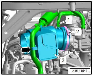
- Remove the bolts -arrows- for the Transmission Fluid Cooling Valve -N509--3-.
- Disconnect the connector -1-.
 Note
Note
Place a cloth underneath to catch any escaping coolant.
- Loosen the hose clamps -2- to clamp off the coolant hoses with the Hose Clamps - Up To 25mm -3094- and remove them.
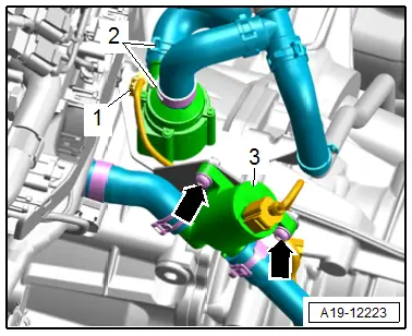
- Remove the nut -2- and free up the right coolant pipe from the transmission -1- on the threaded pin.
- Remove the bolts -arrows- and remove the bracket -4- with the Coolant Recirculation Pump -V50--3-.
- Remove the bolts -5- and remove the Coolant Recirculation Pump -V50- from the bracket.
Installing
Install in reverse order of removal and note the following:
 Note
Note
Secure all hose connections with hose clamps that match the ones used in series production. Refer to the Parts Catalog.
- Install the air filter housing. Refer to → Chapter "Air Filter Housing, Removing and Installing".
 Note
Note
Used coolant cannot be used again.
- Fill with coolant.
Tightening Specifications
- Refer to → Chapter "Overview - Electric Coolant Pump"
- Refer to → Chapter "Overview - Charge Air Hose Connections"
Charge Air Cooling Pump -V188-, Removing and Installing
Special tools and workshop equipment required
- Hose Clamps - Up To 25 mm -3094-
- Hose Clip Pliers -VAS6340-
Removing
- Remove the left front section of the wheel housing liner. Refer to → Body Exterior; Rep. Gr.66; Wheel Housing Liner; Front Wheel Housing Liner, Removing and Installing.
 Note
Note
For clarity, the installation position is shown with the left headlamp removed.
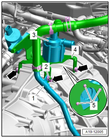
- Disconnect the connector -4-.
 Note
Note
Place a cloth underneath to catch any escaping coolant.
- Disconnect the coolant hose -1- from the Charge Air Cooling Pump -V188- with the Hose Clamps - Up To 25mm -3094-.
- Loosen the clamps -2- and remove the coolant hoses.
- Remove the bolt -4- and remove the retaining bracket.
- Remove the charge air cooling pump.
Installing
Install in reverse order of removal and note the following:
 Note
Note
- Secure all hose connections with hose clamps that match the ones used in series production. Refer to the Parts Catalog.
- Used coolant cannot be used again.
- Fill with coolant.
Tightening Specifications
- Refer to → Chapter "Overview - Electric Coolant Pump"
- Refer to → Body Exterior; Rep. Gr.66; Wheel Housing Liner; Overview - Front Wheel Housing Liner.
Coolant Pump, Removing and Installing
Special tools and workshop equipment required
- Wrench - Pin Type -3212-
Removing
- Drain the coolant. Refer to → Chapter "Coolant, Draining and Filling".
- Remove the front left coolant pipes. Refer to → Chapter "Front Left Coolant Pipes, Removing and Installing".
- Remove the ribbed belt from the coolant pump. Refer to → Chapter "Ribbed Belt, Removing and Installing, Sub-Assembly Ribbed Belt".
- Remove the lock carrier cover. Refer to → Body Exterior; Rep. Gr.63; Front Bumper; Attachments, Removing and Installing.
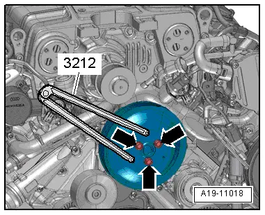
- Remove the bolts -arrows- for the coolant pump ribbed belt pulley by using a Wrench - Pin Type -3212- to counterhold.
- Remove the bolts and remove the ribbed belt pulley.
- Disconnect the vacuum hose -1-.
 Note
Note
Place a cloth underneath to catch any leaking coolant.
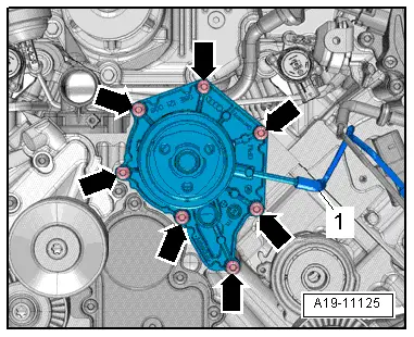
- Remove the bolts -arrows- and remove the coolant pump.
Installing
Install in reverse order of removal and note the following:
- Clean any oil or grease off the sealing surfaces.
- Install the left front coolant pipes. Refer to → Chapter "Front Left Coolant Pipes, Removing and Installing".
- Install the ribbed belt. Refer to → Chapter "Ribbed Belt, Removing and Installing, Sub-Assembly Ribbed Belt".
- Install the lock carrier cover. Refer to → Body Exterior; Rep. Gr.63; Front Bumper; Attachments, Removing and Installing.
 Note
Note
Used coolant cannot be used again.
- Fill with coolant.
Tightening Specifications
- Refer to → Chapter "Overview - Coolant Pump/Coolant Thermostat"
Coolant Thermostat, Removing and Installing
Removing
 Caution
This procedure contains mandatory replaceable parts. Refer to component overview prior to starting procedure.
Mandatory Replacement Parts
- Seal - Coolant thermostat
- Remove the front right coolant pipe. Refer to → Chapter "Right Front Coolant Pipe, Removing and Installing".
 Note
Note
Place a cloth underneath to catch any leaking coolant.
- Remove the bolts -arrows-.
- Remove the coolant thermostat with the connections.
Installing
Install in reverse order of removal and note the following:
 Note
Note
When removing and installing the coolant thermostat, make sure that the thermostat needle is installed correctly (conical end is inserted in the coolant thermostat wax thermostatic element). If necessary, push the thermostat needle all the way into the wax thermostatic element.
 Note
Note
Replace the seal after removal.
- Install the right front coolant pipe. Refer to → Chapter "Right Front Coolant Pipe, Removing and Installing".
Tightening Specifications
- Refer to → Chapter "Overview - Coolant Pump/Coolant Thermostat"
Engine Coolant Temperature Sensor -G62-, Removing and Installing
 Caution
This procedure contains mandatory replaceable parts. Refer to component overview prior to starting procedure.
Mandatory Replacement Parts
- O-ring - Engine coolant temperature sensor
Removing
- The engine is cold.
- Remove the engine cover. Refer to → Chapter "Engine Cover, Removing and Installing".
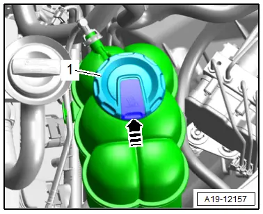
- To reduce the residual pressure in the cooling system, briefly open the coolant expansion tank cap -1- by pressing the retainer in direction of -arrow-.
- Reinstall the cap until it engages.
- Disconnect the connector -2-.
 Note
Note
Place a cloth underneath to catch any leaking coolant.
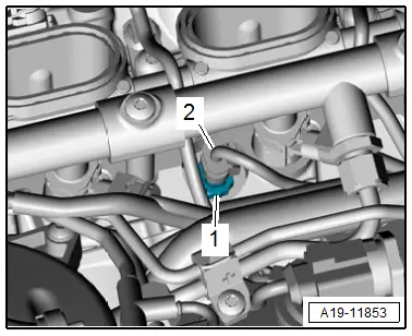
- Remove the clip -1- and the Engine Coolant Temperature Sensor -G62-.
Installing
Install in reverse order of removal and note the following:
 Note
Note
- Replace the O-ring after removing.
- To prevent loosing coolant, install the new Engine Coolant Temperature Sensor -G62- immediately into the front coolant pipe.
- Install the engine cover. Refer to → Chapter "Engine Cover, Removing and Installing".
- Check the coolant level.
Engine Temperature Control Temperature Sensor -G694-, Removing and Installing
Special tools and workshop equipment required
- 15 mm twelve point socket with corner extension, commercially available
 Note
Note
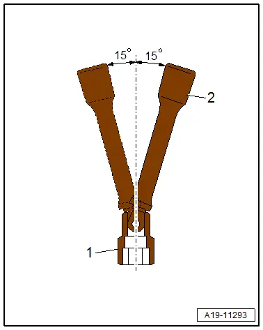
To keep from having to remove the fuel rail use a 15 mm twelve point socket -1- with a corner extension -2-.
Removing
- Remove the supercharger. Refer to → Chapter "Supercharger, Removing and Installing".
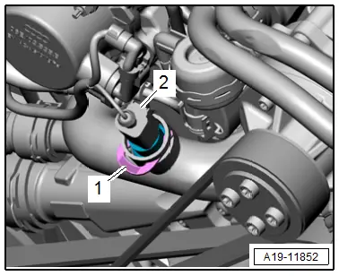
- Disconnect the connector -2-.
- Remove the Engine Temperature Control Sensor -G694--1-.
Installing
Install in reverse order of removal and note the following:
- Install the supercharger. Refer to → Chapter "Supercharger, Removing and Installing".
Tightening Specifications
- Refer to → Chapter "Overview - Engine Coolant Temperature Sensor"
Coolant Valves, Removing and Installing
Special tools and workshop equipment required
- Hose Clamps - Up To 25 mm -3094-
- Hose Clip Pliers -VAS6340-
Removing
- Remove the air filter housing. Refer to → Chapter "Air Filter Housing, Removing and Installing".
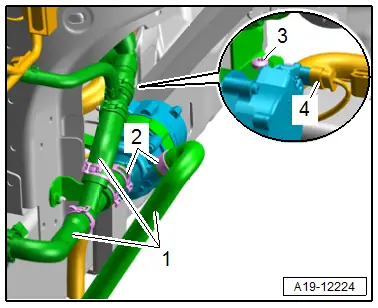
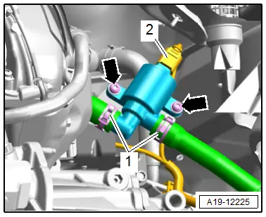
- Disconnect the connector -2-.
- Remove the bolts -arrows-.
 Note
Note
Place a cloth underneath to catch any escaping coolant.
- Loosen the hose clamps -1-, then clamp off the coolant hoses with the Hose Clamps - Up To 25mm -3094- and then remove them.
- Remove the Transmission Fluid Cooling Valve -N509-.
Installing
Install in reverse order of removal and note the following:
 Note
Note
Secure all hose connections with hose clamps that match the ones used in series production. Refer to the Parts Catalog.
- Install the air filter housing. Refer to → Chapter "Air Filter Housing, Removing and Installing".
 Note
Note
Used coolant cannot be used again.
- Fill with coolant.
Tightening Specifications
- Refer to → Chapter "Overview - Coolant Pump/Coolant Thermostat"
- Refer to → Body Exterior; Rep. Gr.66; Noise Insulation; Overview - Noise Insulation.

