Audi Q7: Coolant Pipes, Removing and Installing
Front Left Coolant Pipe, Removing and Installing
Special tools and workshop equipment required
- Hose Clip Pliers -VAS6340-
Removing
 WARNING
There is a risk of injury if the radiator fan turns on by itself.
The radiator fans can come on by itself even when the ignition is turned off, such as when heat builds up in the engine compartment.
- Drain the coolant. Refer to → Chapter "Coolant, Draining and Filling".
- Remove the reinforcement brace. Refer to → Body Exterior; Rep. Gr.50; Lock Carrier; Overview - Lock Carrier.
- Remove the front left coolant pipes. Refer to → Chapter "Front Left Coolant Pipes, Removing and Installing".
- Remove the ribbed belt from the tensioner. Refer to → Chapter "Ribbed Belt, Removing and Installing, Sub-Assembly Ribbed Belt".
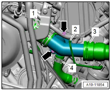
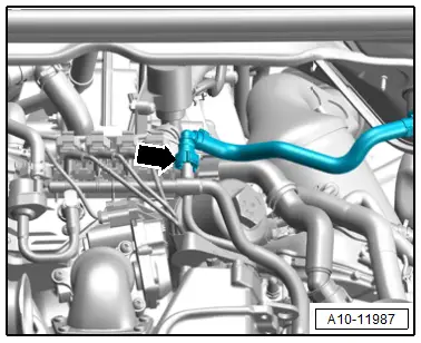
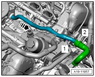
- Free up the vacuum hose -2-.
- Open the clamp -3- and remove the coolant hose.
- Remove the bolts -arrows- loosen the hose clamps -1 and 4- and remove the left front coolant pipe.
Installing
Install in reverse order of removal and note the following:
 Note
Note
- Replace the seal after removal.
- Secure all hose connections with hose clamps that match the ones used in series production. Refer to the Parts Catalog.
- Install the ribbed belt. Refer to → Chapter "Ribbed Belt, Removing and Installing, Sub-Assembly Ribbed Belt".
- Install the left front coolant pipes. Refer to → Chapter "Front Left Coolant Pipes, Removing and Installing".
- Connect the coolant hoses with the connector coupling. Refer to → Fig. "Connect the Coolant Hose to the Connector Coupling".
 Note
Note
Used coolant cannot be used again.
- Fill with coolant.
Tightening Specifications
- Refer to → Chapter "Overview - Coolant Pipes"
- Refer to → Body Exterior; Rep. Gr.50; Lock Carrier; Overview - Lock Carrier.
Front Left Coolant Pipes, Removing and Installing
Special tools and workshop equipment required
- Hose Clamps - Up To 25 mm -3094-
- Container of the Coolant Collection System -VAS5014- or the Shop Crane - Drip Tray -VAS6208-
- Hose Clip Pliers -VAS6340-
- Hose Clip Pliers -VAS6362-
Removing
 WARNING
There is a risk of injury if the radiator fan turns on by itself.
The radiator fans can come on by itself even when the ignition is turned off, such as when heat builds up in the engine compartment.
- Remove the engine cover. Refer to → Chapter "Engine Cover, Removing and Installing".
- Remove the front noise insulation. Refer to → Body Exterior; Rep. Gr.66; Noise Insulation; Noise Insulation, Removing and Installing.
 WARNING
Risk of scalding due to hot steam and hot coolant.
- The cooling system is under pressure when the engine is warm.
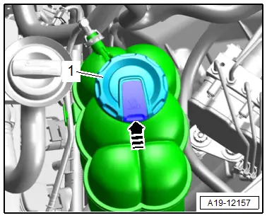
- Cover the coolant expansion tank cap with a cloth and carefully open it to reduce the pressure.
- Open the cover -1- for the coolant expansion tank by pressing the retainer in direction of -arrow-.

- Place the container of the Coolant Collection System -VAS5014- or the Shop Crane - Drip Tray -VAS6208- underneath.
 Note
Note
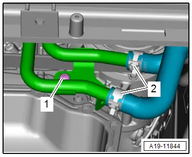
The engine is not shown in the following illustrations.
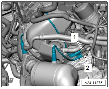
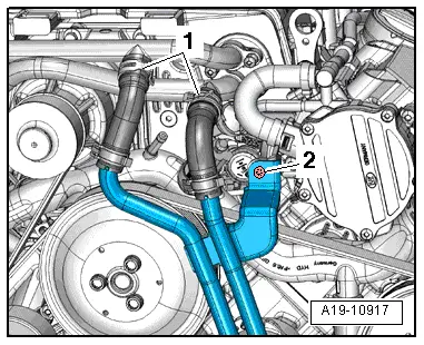
- Loosen the hose clamps -2-, clamp off the coolant hoses with the Hose Clamps - Up To 25mm -3094- and remove them from the left front coolant pipes.
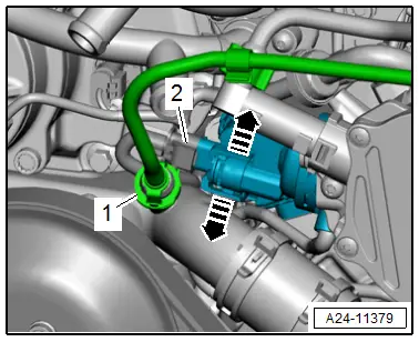
- Remove the bolt -1-.
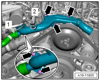
- Loosen the hose clamps -1- and remove the coolant hoses from the coolant pipes on the supercharger.
- Remove the bolt -2-.
- Remove the front left coolant pipes downward.

Installing
Install in reverse order of removal and note the following:
 Note
Note
Secure all hose connections with hose clamps that match the ones used in series production. Refer to the Parts Catalog.
- Install the engine cover. Refer to → Chapter "Engine Cover, Removing and Installing".
 Note
Note
Used coolant cannot be used again.
- Fill with coolant.
Tightening Specifications
- Refer to → Chapter "Overview - Coolant Pipes"
- Refer to → Body Exterior; Rep. Gr.66; Noise Insulation; Overview - Noise Insulation.
Right Front Coolant Pipe, Removing and Installing
 Caution
This procedure contains mandatory replaceable parts. Refer to component overview prior to starting procedure.
Mandatory Replacement Parts
- Seals - Right front coolant pipe
Special tools and workshop equipment required
- Hose Clip Pliers -VAS6362-
Removing
- Remove the supercharger. Refer to → Chapter "Supercharger, Removing and Installing".
- Remove the front left coolant pipe. Refer to → Chapter "Front Left Coolant Pipe, Removing and Installing".
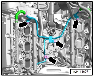
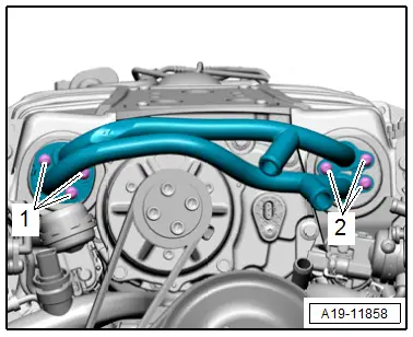
- Open the clamp -1- and remove the coolant line.
- Disconnect the connector -2-.
- Release the catches in direction of -arrows- and remove the Intake Manifold Runner Position Sensor -G336-.
- Disconnect the connector -2-.
- Open the clamp -1- and remove the coolant hose.
- Remove the bolts -arrows- and the right front coolant pipe.
Installing
Install in reverse order of removal and note the following:
 Note
Note
- Replacing the seals after removal.
- Secure all hose connections with hose clamps that match the ones used in series production. Refer to the Parts Catalog.
- Connect the coolant line and coolant hose with the connector coupling. Refer to → Fig. "Connect the Coolant Hose to the Connector Coupling".
- Install the left front coolant pipe. Refer to → Chapter "Front Left Coolant Pipe, Removing and Installing".
- Install the supercharger. Refer to → Chapter "Supercharger, Removing and Installing".
 Note
Note
Used coolant cannot be used again.
- Fill with coolant.
Tightening Specifications
- Refer to → Chapter "Overview - Coolant Pipes"
Left Coolant Pipe, Removing and Installing
Special tools and workshop equipment required
- Hose Clip Pliers -VAS6362-
Removing
- Drain the coolant. Refer to → Chapter "Coolant, Draining and Filling".
- Remove the engine cover. Refer to → Chapter "Engine Cover, Removing and Installing".
- Free up the wiring harness and push it to the side.
- Disconnect the brake booster vacuum hose -arrow- by pressing the release buttons on both sides.
- Remove the connector -1- for the Heated Oxygen Sensor 2 -G108- from the bracket, disconnect it and free up the wire.
 Note
Note
Ignore -2-.
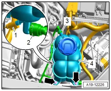
- Remove the bolts -arrows- and remove the coolant expansion tank -4- upward from the bracket.
- Disconnect the connector -1-.
- Open the clamps -2 and 3- and remove the coolant hoses form the coolant expansion tank.
- Remove the Camshaft Position Sensor 4 -G301-. Refer to → Chapter "Camshaft Position Sensor, Removing and Installing".
- Free up the wiring harness.
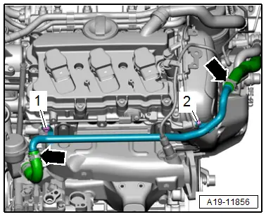
- Remove the coolant hoses, to do so, loosen the hose clamps -arrows-.
- Remove the bolt -1- and the nut -2- and then remove the left coolant pipe upward.
Installing
Install in reverse order of removal and note the following:
 Note
Note
Secure all hose connections with hose clamps that match the ones used in series production. Refer to the Parts Catalog.
- Install the engine cover. Refer to → Chapter "Engine Cover, Removing and Installing".
- Connections and wire routing. Refer to → Wiring diagrams, Troubleshooting & Component locations.
 Note
Note
Used coolant cannot be used again.
- Fill with coolant.
Tightening Specifications
- Refer to → Chapter "Overview - Coolant Pipes"
- Refer to → Chapter "Overview - Ignition System"
Upper Coolant Pipe, Removing and Installing
 Caution
This procedure contains mandatory replaceable parts. Refer to component overview prior to starting procedure.
Mandatory Replacement Parts
- O-ring - Upper coolant pipe
Removing
 Note
Note
During installation, all cable ties must be installed at the same location.
- Drain the coolant. Refer to → Chapter "Coolant, Draining and Filling".
- Remove the supercharger. Refer to → Chapter "Supercharger, Removing and Installing".
- Remove the bolts -arrows- for the fuel line.
 Note
Note
Place a cloth underneath to catch any escaping coolant.
- Open the clamp -2- and remove the coolant hose form the coolant pipe.
- Remove the bolt -1- and remove the coolant pipe toward the rear from the cylinder block in direction of -arrow- at the same time lift the fuel line slightly.
 Note
Note
Do not change the shape of the fuel line.
Installing
Install in reverse order of removal and note the following:
 Note
Note
Replace the O-ring after removing.
- Clean and smooth the O-ring sealing surface.
- Coat the O-ring with coolant and slide it onto the coolant pipe.
- Connect the coolant hose to the connector coupling. Refer to → Fig. "Connect the Coolant Hose to the Connector Coupling".
- Install the fuel line. Refer to → Chapter "Fuel Line, Removing and Installing".
- Install the supercharger. Refer to → Chapter "Supercharger, Removing and Installing".
 Note
Note
Used coolant cannot be used again.
- Fill with coolant.
Tightening Specifications
- Refer to → Chapter "Overview - Coolant Pipes"
Supercharger Coolant Pipes, Removing and Installing
Special tools and workshop equipment required
- Hose Clamps - Up To 25 mm -3094-
- Container of the Coolant Collection System -VAS5014- or the Shop Crane - Drip Tray -VAS6208-
- Hose Clip Pliers -VAS6362-
 Caution
This procedure contains mandatory replaceable parts. Refer to component overview prior to starting procedure.
Mandatory Replacement Parts
- Seals - Supercharger coolant pipes
Removing
- Remove the engine cover. Refer to → Chapter "Engine Cover, Removing and Installing".
 WARNING
Risk of scalding due to hot steam and hot coolant.
- The cooling system is under pressure when the engine is warm.
- Cover the coolant expansion tank cap with a cloth and carefully open it to reduce the pressure.
- Open the cover -1- for the coolant expansion tank by pressing the retainer in direction of -arrow-.
- Remove the front noise insulation. Refer to → Body Exterior; Rep. Gr.66; Noise Insulation; Noise Insulation, Removing and Installing.
- Place the container of the Coolant Collection System -VAS5014- or the Shop Crane - Drip Tray -VAS6208- underneath.
- Loosen the hose clamps -1-, clamp off the coolant hoses with the Hose Clamps - Up To 25mm -3094- and remove them from the coolant pipes on the supercharger.
 Note
Note
Ignore -2-.
- Free up the wiring harness.
- Remove the bolts -1 and 2- and remove the coolant pipes from the supercharger.
Installing
Install in reverse order of removal and note the following:
 Note
Note
- Replacing the seals after removal.
- Secure all hose connections with hose clamps that match the ones used in series production. Refer to the Parts Catalog.
- Install the engine cover. Refer to → Chapter "Engine Cover, Removing and Installing".
 Note
Note
Used coolant cannot be used again.
- Fill with coolant.
Tightening Specifications
- Refer to → Chapter "Overview - Coolant Pipes"
- Refer to → Body Exterior; Rep. Gr.66; Noise Insulation; Overview - Noise Insulation.
Left Coolant Pipe on Transmission, Removing and Installing
Special tools and workshop equipment required
- Hose Clamps - Up To 25 mm -3094-
- Hose Clip Pliers -VAS6340-
Removing
- Remove the air filter housing. Refer to → Chapter "Air Filter Housing, Removing and Installing".
- Remove the rear noise insulation. Refer to → Body Exterior; Rep. Gr.66; Noise Insulation; Noise Insulation, Removing and Installing.
 Note
Note
Place a cloth underneath to catch any escaping coolant.
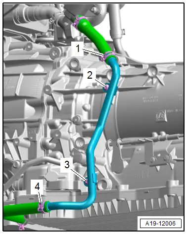
- Loosen the hose clamps, then clamp off the coolant hoses -1 and 4- with the Hose Clamps - Up To 25mm -3094- and then remove them.
- Remove the bolts -2 and 3- and then remove the coolant pipe on the left side of the transmission.
Installing
Install in reverse order of removal and note the following:
 Note
Note
Secure all hose connections with hose clamps that match the ones used in series production. Refer to the Parts Catalog.
- Install the air filter housing. Refer to → Chapter "Air Filter Housing, Removing and Installing".
 Note
Note
Used coolant cannot be used again.
- Fill with coolant.
Tightening Specifications
- Refer to → Chapter "Overview - Coolant Pipes"
- Refer to → Body Exterior; Rep. Gr.66; Noise Insulation; Overview - Noise Insulation.
Right Coolant Pipe on Transmission, Removing and Installing
Special tools and workshop equipment required
- Hose Clamps - Up To 25 mm -3094-
- Hose Clip Pliers -VAS6340-
Removing
- Remove the air filter housing. Refer to → Chapter "Air Filter Housing, Removing and Installing".
- Remove the right subframe shield. Refer to → Suspension, Wheels, Steering; Rep. Gr.40; Subframe; Subframe Shield, Removing and Installing.
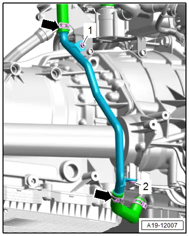
- Remove the bolt -2- and the nut -1-.
- Loosen the hose clamps -arrows-, then clamp off the coolant hoses with the Hose Clamps - Up To 25mm -3094- and remove the hoses.
- Remove the coolant pipe on the right side of the transmission.
Installing
Install in reverse order of removal and note the following:
 Note
Note
Secure all hose connections with hose clamps that match the ones used in series production. Refer to the Parts Catalog.
- Install the air filter housing. Refer to → Chapter "Air Filter Housing, Removing and Installing".
 Note
Note
Used coolant cannot be used again.
- Fill with coolant.
Tightening Specifications
- Refer to → Chapter "Overview - Coolant Pipes"
- Refer to → Suspension, Wheels, Steering; Rep. Gr.40; Subframe; Overview - Subframe.

