Audi Q7: Coolant Recirculation Pump -V50-, Function
 Note
Note
- The Coolant Recirculation Pump -V50- is currently not installed in all vehicles. Refer to → Rep. Gr.19; Coolant System/Coolant; Connection Diagram - Coolant Hoses. If a parking heater is installed as optional equipment in vehicles, a Coolant Recirculation Pump -V50- may not be installed. The Recirculation Pump -V55- installed in vehicles with a parking heater assumes this function. The discontinuation of the coolant recirculation pump -V50- has not been implemented in all vehicles. Refer to Vehicle Diagnostic Tester in the "Guided Fault Finding" function and refer to → Wiring diagrams, Troubleshooting & Component locations.
- The activation of the Coolant Recirculation Pump -V50- varies. For most vehicles the respective Engine Control Module -J623- (or from the Vehicle Electrical System Control Module -J519-) is activated at the request of the Front A/C Display Control Head -E87-. Refer to → Wiring diagrams, Troubleshooting & Component locations.
Function
- The Coolant Recirculation Pump -V50--A- supports the engines own coolant pump during coolant recirculation. It is activated by the Engine Control Module -J623- (or from the Vehicle Electrical System Control Module -J519-) at the request of the Front A/C Display Control Head -E87- to ensure sufficient and even coolant flow through the heater core(s) of the heating and A/C system. Refer to Vehicle Diagnostic Tester in the "Guided Fault Finding" function.
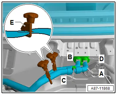
- When the Coolant Recirculation Pump -V50--A- is on, the coolant is drawn in by the engine via coolant hose -C- and is pumped via coolant hose -D- to the heater cores of the heater and A/C units. Via the heat exchangers in the heater and A/C units (front and rear) and the Coolant Shut-Off Valve -N82-/the Heater Coolant Shut-Off Valve -N279- (depending on the engine version and the vehicle equipment), it flows back to the engine. Refer to → Chapter "Incorporating the Heating and A/C System in the Coolant Circuit".
- The Coolant Recirculation Pump -V50--A- is activated when the ignition is turned on, depending on the coolant temperature and the adjustment on the Front A/C Display Control Head -E87- from Engine Control Module -J623- (or from Vehicle Electrical System Control Module -J519-). Refer to Vehicle Diagnostic Tester in the "Guided Fault Finding" function and refer to → Wiring diagrams, Troubleshooting & Component locations.
- Depending on the version of the vehicle the Coolant Recirculation Pump -V50--A- is also activated by the request from the Front A/C Display Control Head -E87- from the Engine Control Module -J623- (or from the vehicle Electrical System Control Module -J519-) when the parking heater is on or in the "residual heat function". Refer to Vehicle Diagnostic Tester in the "Guided Fault Finding" function.
- On vehicles with a "Start/Stop System" the Coolant Recirculation Pump -V50--A- (and the Coolant Shut-Off Valve - N82-) are activated by a request from the Front A/C Display Control Head -E87-. The Heater Coolant Shut-Off Valve - N279- (and the Recirculation Pump - V55- are if equipped activated via the Auxiliary Heater Control Module -J364- are activated by a request from the Front A/C Display Control Head -E87-. Refer to → Wiring diagrams, Troubleshooting & Component locations and the Vehicle Diagnostic Tester"Guided Fault Finding" function.
- If errors are determined on these components and in the Front A/C Display Control Head -E87- no activation is stored. Therefore pay attention to the version, coding and adaptation of the Front A/C Display Control Head -E87-. Refer to Vehicle Diagnostic Tester in the "Guided Fault Finding" function.
- Coolant Recirculation Pump -V50-, removing and installing. Refer to → Rep. Gr.19; Coolant Pump/Coolant Thermostat; Electric Coolant Pump, Removing and Installing.
- Heater Coolant Shut-Off Valve -N279-, Removing and installing. Refer to → Chapter "Heater Coolant Shut-Off Valve -N279- Function".
Heater Coolant Shut-Off Valve -N279- Function
The Heater Coolant Shut-Off Valve -N279- is activated from the Auxiliary Heater Control Module - J364- according to the coolant temperature and the setting request. Refer to Vehicle Diagnostic Tester in the "Guided Fault Finding" function.
 Note
Note
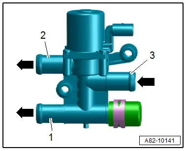
- The closure cap can depending on the vehicle version also be installed on the connection -1-.
- If the Heater Coolant Shut-Off Valve -N279- is not activated the coolant flows over the connections -2 and 3-.
- If the Heater Coolant Shut-Off Valve -N279- is activated the coolant flows over the connections -1 and 3-.
 Note
Note
- Depending on the ambient temperature and the heating and A/C system heat exchanger heat supplied the activation of the Heater Coolant Shut-Off Valve -N279- remains for a longer time in the different operating conditions.
- There are different versions of the Heater Coolant Shut-Off Valve -N279-. Pay attention to the correct allocation. Refer to the Parts Catalog.
- The display in the "read the measured values" function for the activation of the Heater Coolant Shut-Off Valve -N279- is different and depends on the version of the vehicle and the Auxiliary Heater Control Module -J364-. On this vehicle currently for example with 100% it is displayed that 100% of the coolant is delivered in the small circuit and the Heater Coolant Shut-Off Valve -N279- is activated. Refer to Vehicle Diagnostic Tester in the "Guided Fault Finding" function.
Coolant Circuit, Bleeding
 Note
Note
- The removal of A/C system components is described in this repair manual in such a way that only a small amount of air enters the coolant circuit. Therefore, it is not necessary to bleed the coolant circuit completely after removing and installing these components.
- However, if a large quantity of coolant has escaped due to another complaint, for example, due to a leaking hose, the coolant circuit must be completely bled with the Cooling System Charge Unit -VAS6096-. Refer to → Rep. Gr.19; Coolant System/Coolant; Coolant, Draining and Filling.
- After bleeding and charging the coolant circuit using the Cooling System Charge Unit -VAS6096-, the section of the coolant circuit of the heating and A/C system (heater core and associated hoses) is to be post-bled again via the bleeder screw -C-.
Prerequisite
- The cooling circuit is essentially filled with coolant, there are only a few air bubbles in only a few locations of the cooling circuit.
 Note
Note
- Since only a small amount of air entered the coolant circuit during installation of the A/C system components (for example, the heater and A/C unit in the front or rear A/C unit, the Coolant Recirculation Pump -V50-, the Coolant Shut-Off Valve -N82-, etc.) and the circuit was charged again during installation of the components, only a small amount of air is in the coolant circuit. Therefore, it is sufficient to set the A/C system to maximum heating output when the engine is at operating temperature (so that the Coolant Recirculation Pump -V50- is activated) and to run the engine for several minutes at a high idling speed (approximately 2000 RPM) to completely bleed the coolant circuit.
- When bleeding the coolant circuit, take special care to ensure complete bleeding of the heater core. If there are still air bubbles in the heater cores, they may cause the customer to complain of insufficient heating performance in winter or different air temperature from vents at the same setting in control mode. Refer to → Chapter "A/C System Temperature Door Heat Output Activation, Checking".
Bleeding
- Fill coolant into coolant expansion tank up to top marking. Refer to → Rep. Gr.19; Coolant System/Coolant; Coolant, Draining and Filling.
- Start the engine and let it run until it reaches operating temperature.
- Set the Front A/C Display Control Head -E87- (and the Rear A/C Display Control Head -E265-, if present) to maximum heat output (for example, temperature preset on "HI") for the driver side and front passenger side.
- Set the fresh air blower speed to approximately 30% of maximum output on the Front A/C Display Control Head -E87- (and the Rear A/C Display Control Head -E265- if present).
- The Fresh Air Blower -V2- and the Rear Fresh Air Blower -V80- operate at a speed in the lower output range.
- On vehicles with a parking heater, switch it on briefly. Refer to → Heating, Ventilation, and Air Conditioning; Rep. Gr.00; General Information.
- Let engine run approximately two minutes at increased idle speed (approximately 2000 up to 2500 RPM).
- Turn off the ignition and check the coolant level in coolant expansion tank, adding coolant if necessary. Refer to → Rep. Gr.19; Coolant System/Coolant; Coolant, Draining and Filling.
 WARNING
The coolant circuit is under pressure. When opening the coolant expansion tank, hot steam or hot coolant may flow out. Therefore, cover the sealing cap with a cloth and open carefully.

