Audi Q7: Coolant System/Coolant
Connection Diagram - Coolant Hoses
Connection Diagram - Coolant Hoses, Vehicles without Parking Heater
 Note
Note
- Blue = large coolant circuit.
- Red = small coolant circuit.
- Orange = coolant circuit for the charge air cooler.
- Brown = heating circuit.
- Green = coolant circuit for the transmission.
- The arrows show the coolant flow direction.
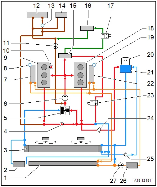
1 - Charge Air Cooling Circuit Cooler
2 - Coolant Auxiliary Cooler
- Equipped on some models
3 - Radiator
4 - Engine Coolant Temperature Sensor -G62-
5 - Coolant Thermostat
6 - Coolant Pump
- Vacuum controlled by the Cylinder Head Coolant Valve -N489-
7 - Right Charge Air Cooler
- In supercharger housing
8 - Bleed Screw
9 - Cylinder Head
- Cylinder Bank 1 (Right)
10 - Engine Temperature Control Sensor -G694-
11 - Coolant Recirculation Pump -V50-
12 - Front Heater Core for the Heater
13 - Bleed Screw
14 - Rear Heater Core for the Heater
- Equipped on some models
15 - Engine Oil Cooler
16 - ATF Cooler
17 - Transmission Fluid Cooling Valve -N509-
18 - Cylinder Head
- Cylinder Bank 2 (Left):
19 - Bleed Screw
20 - Cap
- Check the pressure relief valve.
21 - Coolant Expansion Tank
22 - Left Charge Air Cooler
- In supercharger housing
23 - Coolant Shut-Off Valve
- Vacuum-controlled by the Cooling Circuit Solenoid Valve -N492-
24 - Check Valve
- Inside the coolant hose
25 - Check Valve
- Inside the coolant hose
26 - Coolant Auxiliary Cooler
- Equipped on some models
27 - Charge Air Cooling Pump -V188-
Cooling System, Checking for Leaks
Special tools and workshop equipment required
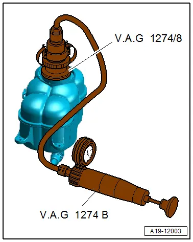
- Cooling System Tester -VAG1274B-
- Cooling System Tester - Adapter -VAG1274/8-
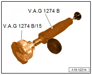
- Adapter -VAG1274B/15-, not illustrated
Procedure
- Engine at operating temperature.
 WARNING
The cooling system is under pressure when the engine is warm. Risk of scalding due to hot steam and hot coolant.
Scalding the skin and other parts of the body is possible.
- Wear safety gloves.
- Wear protective eyewear.
- Reduce the pressure by covering the coolant expansion tank cap with a cloth and carefully opening it.
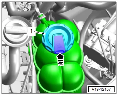
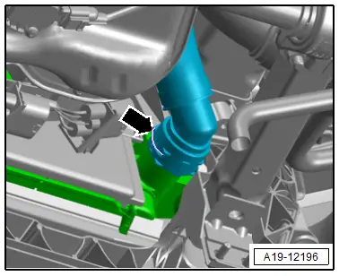
- Open the cover -1- for the coolant expansion tank by pressing the retainer in direction of -arrow-.
- Position the Cooling System Tester -VAG1274B- with the Cooling System Tester - Adapter -VAG1274/8- on the coolant expansion tank.
- Generate approximately 1.5 bar (21.75 psi) pressure using the cooling system tester hand pump.
- The pressure must not drop more than 0.2 bar (2.9 psi) within 10 minutes.
- If the pressure falls more than 0.2 bar (2.9 psi), search for leaks and correct the problem.
 Note
Note
The pressure decrease of 0.2 bar (2.9 psi) within 10 minutes is a condition of the cooling of the coolant. The colder the engine the more the pressure decrease. If necessary repeat the test with the engine cold.
Pressure Relief Valve in Cap, Checking
- Position the Cooling System Tester -VAG1274B- with the Adapter -VAG1274B/15- on the cap.
- Generate pressure with the cooling system tester hand pump.
- The pressure release valve must open at 1.4 to 1.6 bar (20.30 to 23.20 psi).
- If pressure relief valve does not open as specified, replace the cap.
Coolant, Draining and Filling
Special tools and workshop equipment required
- Cooling System Tester - Adapter -VAG1274/8-
- Cooling System Tester - Adapter -VAG1274/10-
- Cooling System Charge Kit -VAS6096-
- Coolant Collection System -VAS5014- or Shop Crane - Drip Tray -VAS6208-
- Hose Clip Pliers -VAS6362-
- Refractometer -T10007A-
Draining
 WARNING
There is a risk of injury if the radiator fan turns on by itself.
The radiator fans can come on by itself even when the ignition is turned off, such as when heat builds up in the engine compartment.
Risk of scalding due to hot steam and hot coolant.
- The cooling system is under pressure when the engine is warm.
- Cover the coolant expansion tank cap with a cloth and carefully open it to reduce the pressure.
- Open the cover -1- for the coolant expansion tank by pressing the retainer in direction of -arrow-.
- Remove the noise insulations. Refer to → Body Exterior; Rep. Gr.66; Noise Insulation; Noise Insulation, Removing and Installing.

- Place the container of the Coolant Collection System -VAS5014- or the Shop Crane - Drip Tray -VAS6208- underneath.
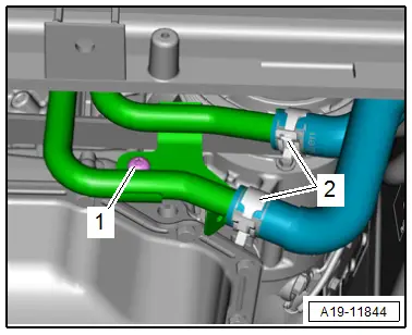
- Lift the clamp -arrow- and remove the coolant hose from the radiator and drain the coolant.
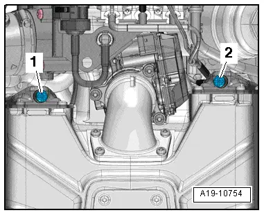
- Loosen the clamps -2- and drain any remaining coolant to remove the coolant hoses from the front coolant pipes.
 Note
Note
Ignore -1-.
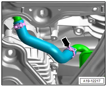
- Remove the coolant hose from the right coolant pipe on the transmission by loosening the hose clamp -arrow- and letting the coolant drain out.
- Reattach the coolant hoses. For versions with a connector coupling, Refer to → Fig. "Connect the Coolant Hose to the Connector Coupling".
Filling
- Ignition switched off.
 Caution
Only mix distilled water with coolant additives. Using distilled water provides optimum corrosion protection.
 Note
Note
- The mixture of the water used greatly influences the effectiveness of the coolant. The water quality to be used is based on the contents, which can be specific to a country or even a region. Distilled water fulfills all requirements. For this reason, use distilled water when adding coolant or filling coolant for the first time.
- Use only coolant additives listed. Refer to the Parts Catalog. Other coolant additives may above all reduce the corrosion protection effect significantly. The damage resulting from this may lead to loss of coolant and consequently to severe engine damage.
- Coolant with the correct mixture ratio prevents freezing and corrosion damage and calcium deposits. Additionally, the boiling temperature will be raised. For this reason the cooling system must be filled with coolant additive year-round.
- Because of its high boiling point, the coolant contributes to engine reliability under heavy engine loads, particularly in countries with tropical climates.
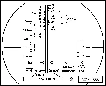
- The Refractometer -T10007A- MUST be used to determine the current freeze protection value.
- Freeze protection must be assured down to minimum -25 ºC (-13 ºF) (in arctic climatic countries down to approximately -36 ºC (-32.8 ºF) ). The freeze protection may only be increased, when stronger freeze protection is needed due to the climate. But only down to -48 ºC (-54 ºF), otherwise the effectiveness of the coolant decreases.
- The coolant concentration must not be reduced by adding water even in warmer seasons and in warmer countries. The frost protection must be at least -25 ºC (-13 ºF).
- Read the freeze protection value on the scale for the coolant additive that has been added.
- The temperature on the Refractometer -T10007A- corresponds to the "freezing point". At this temperature, ice crystals may begin to form in the coolant.
- Used coolant cannot be used again.
- Only use water/coolant additive to lubricate the coolant hoses.
Coolant Mixture Ratio
- Coolant (40%) and distilled water (60%) for freeze protection down to -25 ºC (-13 ºF)
- Coolant (50%) and distilled water (50%) for freeze protection down to -36 ºC (-32.8 ºF)
- Coolant. Refer to the Parts Catalog.
Procedure
- Fill the coolant reservoir on the Cooling System Charge Kit -VAS6096- with at least 15 liters (15.85 quarts) of premixed coolant with the proper mixture ratio.
- Install the Cooling System Tester - Adapter -VAG1274/8- on the coolant expansion tank.
- Attach the Cooling System Charge Kit -VAS6096- on the Cooling System Tester - Adapter -VAG1274/8-.
- Place the drain hose -1- in a small container -2-.
 Note
Note
A small amount of coolant which should be collected is drawn off with the discharged air.
- Close valves -A- and -B- by turning lever at a right angle to the flow direction.
- Connect the hose -3- to compressed air.
- 6 to 10 bar (87.02 to 145.03 psi) positive pressure.
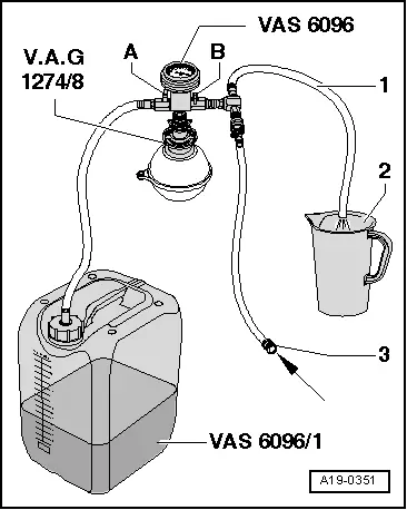
- Open the valve -B- by turning the lever in the flow direction.
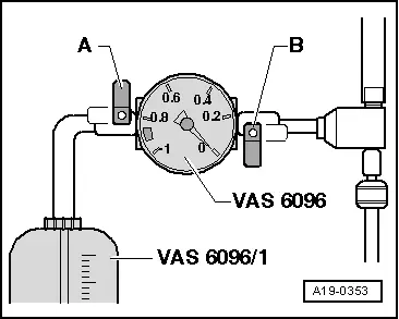
- The suction jet pump generates pressure in the coolant system; indicator on display instrument must move into green area.
- Briefly open the valve -A- by turning the lever in the flow direction so that the hose on the Cooling System Charge Kit -VAS6096- coolant reservoir fills with coolant.
- Close the valve -A- again.
- Leave the valve -B- open another two minutes.
- More pressure is generated in the coolant system by the suction jet pump; indicator on display instrument must stay in the green area.
- Close the valve -B-.
- Needle in the display instrument must remain in the green region, then the sufficient vacuum in the cooling system is obtained for the upcoming filling.
 Note
Note
- If the needle stands below the green area, repeat the procedure.
- If the pressure falls, check the coolant system for leaks.
- Remove the pressure hose.
- Open the valve -A-.
- Coolant is extracted from the Cooling System Charge Kit -VAS6096- coolant reservoir by pressure in the coolant system and the system is filled.
- Remove the Cooling System Charge Kit - VAS6096- from the Cooling System Tester - Adapter -VAG1274/8- on coolant expansion tank.
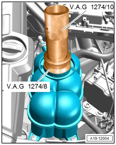
- Connect the Cooling System Tester - Adapter -VAG1274/10- to the Cooling System Tester - Adapter -VAG1274/8-.
- Fill the coolant until the coolant system tester pipe is full. Fill again during the bleeding procedure if necessary.
- Remove the engine cover. Refer to → Chapter "Engine Cover, Removing and Installing".
 Note
Note
Place a cloth underneath to catch any escaping coolant.
- Open the bleed screws -1 and 2- on the charge air coolers one after the other until coolant starts to come out.
- Close the bleeder screws.
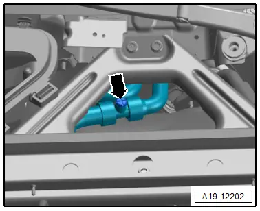
- Remove the seal on the plenum chamber.
- Lift the plenum chamber cover slightly.
- Open the bleeder screw -arrow- on the coolant hose until the coolant starts to come out.
- Close the bleeder screw.
- If the vehicle has a parking heater, switch it on for about 30 seconds.
- Tighten the cap on the coolant expansion tank until it locks into place.
- Install the engine cover. Refer to → Chapter "Engine Cover, Removing and Installing".
- Start the engine.
- Set the temperature to "HI" for all zones and set the fan speed (0).
- Press the AC button to turn off the A/C compressor.
- The LED in the button must not come on.
- Run the engine at 2000 RPM for 3 minutes.
- Run the engine at idle until both large coolant hoses on the radiator are warm.
- Run the engine at 2000 RPM for 2 minutes.
- Turn off engine and allow it to cool off.
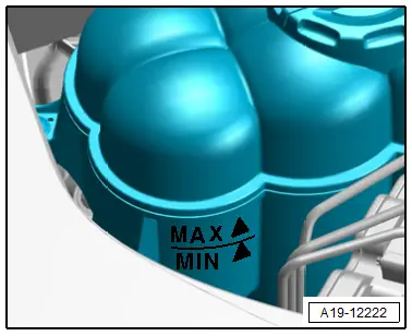
- Check the coolant level.
- The coolant level must be at that MAX marking when the engine is cold.
- Coolant level may be above MAX marking with engine at operating temperature.
Tightening Specifications
- Refer to → Chapter "Overview - Supercharger"
- Refer to → Body Exterior; Rep. Gr.66; Noise Insulation; Overview - Noise Insulation.

