Audi Q7: Cooling Output Test Notes
 Note
Note
- A start-stop system is available for certain engines of this vehicle as optional equipment. Depending on the setting on the Front A/C Display Control Head -E87- (and if present at the Rear A/C Display Control Head -E265-) it can prevent the stop function. If, for example, the "defrost" mode is selected on the Front A/C Display Control Head -E87-, the stop function is not possible or will be interrupted and the engine will start as soon as this operating mode is selected. The same also applies if the difference between the selected specified temperature and the measured actual temperature exceeds a certain value in heating and cooling mode. Refer to Vehicle Diagnostic Tester in the "Guided Fault Finding" function.
- On this vehicle the Coolant Recirculation Pump -V50- is activated not only by an active "Stop function" but also with the engine running for example at the temperature preset "warm" on the Front A/C Display Control Head -E87- ("HI" is displayed in the Front A/C Display Control Head -E87- display). In this vehicle, the Coolant Recirculation Pump -V50- is also activated to support the coolant pump of the motor. Refer to Vehicle Diagnostic Tester in the "Guided Fault Finding" function.
- On a vehicle with a "Low" A/C system (without a Rear A/C Display Control Head -E265-, and without an air distribution housing or a rear heater and A/C unit) the temperature of the air which flows from the front heater and A/C unit to the rear vent is regulated from the Front A/C Display Control Head -E87- so that the air out of the vent for the front area has an average temperature. The target temperature for the air from the vents in the front area is calculated via the setting for the left and right side on the Front A/C Display Control Head -E87- from the Front A/C Display Control Head -E87-. However, if a setting which no longer regulates the temperature (for example, "HI" for maximum heating or "LO" for maximum cooling) is present on the Front A/C Display Control Head -E87-, the temperature of the air from the vents in the front area is no longer regulated. If, for example, maximum heating "HI" is set on the Front A/C Display Control Head -E87- for one side and maximum cooling "LO" for the other side, the air for the vents in the front area is maximally heated.
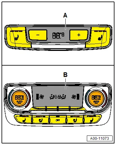
- For vehicles with a "Mid" or "Mix" A/C system (with a rear air distribution housing but without a rear heater and A/C unit), the air temperature and amount of air that is calculated and regulated by the Front A/C Display Control Head -E87- are also influenced by the setting on the Rear A/C Display Control Head -E265- version -A-. However, only the temperature can be adjusted on this Rear A/C Display Control Head -E265-. Refer to → Chapter "Rear A/C Display Control Head -E265-, Removing and Installing, High A/C System".
- For vehicles with a rear heater and A/C unit (on a "High" A/C system), the air temperature and amount of air that is calculated and regulated by the Front A/C Display Control Head -E87- are also influenced by the setting on the Rear A/C Display Control Head -E265-. The temperature for the left and right sides can be adjusted separately on this Rear A/C Display Control Head -E265- version -B-. Refer to → Chapter "Rear A/C Display Control Head -E265-, Removing and Installing, High A/C System".
- Certain A/C system functions can be switched on and off via the MMI (Multi Media Interface) in the "A/C system" function under the "Car"/"Vehicle" menu. The A/C system control can also be influenced via the presets in the MMI (Multi Media Interface) under the "A/C system" function in the "Car"/"Vehicle" menu. Therefore, check the preset in the MMI first in the case there is a problem with these components. Refer to Infotainment/MMI Operating Instructions.
A/C Cooling Output, Testing Requirements
- The ambient temperature is greater than 15 ºC (59 ºF).
- Radiator and condenser are clean (if necessary, clean).
- If a vehicle has electric radiator shutters, their function is OK.
- The ribbed belt, which drives the A/C compressor, is OK and is tensioned correctly. The belt pulley is actually driving the A/C compressor. Refer to → Chapter "Overview - Belt Pulley".
- All air ducts, covers and seals are OK and properly installed.
- Air flow through dust and pollen filter not obstructed by dirt. Refer to → Chapter "Dust and Pollen Filter, Removing and Installing".
- The air intake apparatus (in fresh air and recirculating air mode) is not impaired by soiling or components installed as retrofit.
- The air duct for glove compartment cooling is installed in the glove compartment as specified. Refer to → Chapter "Air Guide for Glove Compartment Cooling, Removing and Installing".
- The vehicle is not exposed to sunlight.
- The engine is warm (the coolant temperature is higher than 80 ºC (176 ºF) ).
- The DTC memory for the Front A/C Display Control Head -E87- and the Rear A/C Display Control Head -E265- on vehicles with a "High" A/C system was checked and erased, the basic setting was performed and the coding for the Front A/C Display Control Head -E87- (and the Rear A/C Display Control Head -E265- on vehicles with a "High" A/C system) was checked. Refer to Vehicle Diagnostic Tester in the "Guided Fault Finding" function.
- The adaptation of the Front A/C Display Control Head -E87- (and the Rear A/C Display Control Head -E265- on a vehicle with a "High" A/C system) was checked. Refer to Vehicle Diagnostic Tester in the "Guided Fault Finding" function.
- The following is set in the MMI (Multi Media Interface) via the "A/C" function in the "Car"/"Vehicle" menu for the regulation of the A/C system: automatic recirculation "off" and "medium" footwell temperature (arrow pointing upward).
 Note
Note
- Depending on vehicle equipment, there are different versions of the A/C system for the Audi Q7. Make sure to use the correct version and pay attention to the allocation of different components. Refer to → Chapter "A/C System Versions" and Parts Catalog.
- The various functions for setting the A/C system in the MMI (Multi Media Interface) ("A/C" function in the "Car" / "Vehicle" menu) differ depending on the A/C system version, the vehicle date of manufacture and the vehicle version (and may not be available for all versions). Refer to Vehicle Operating Instructions.
- All instrument panel vents and the vents in the rear center console and in the B-pillar are open.
- The vent for glove compartment cooling (in the glove compartment) is closed.
- Ensure that the air outlet from the rear footwell vents (under the front seat) is not blocked by floor mats or other objects.
- The hood is closed.
- The engine is running.
On the Front A/C Display Control Head -E87- the following is adjusted:
- "Auto" mode (the indicator lamps in both AUTO buttons illuminate).
- Temperature preselection "cold" for the driver and front passenger side (display "LO" for the driver and front passenger side in the Front A/C Display Control Head -E87- display and in the Multi Media Interface display).
- The A/C compressor is on (the indicator lamp in the A/C MAX button of the Front A/C Display Control Head -E87- comes on).
- Preset for the Fresh Air Blower -V2-"maximum speed" (shown in the display of the Front A/C Display Control Head -E87-).
For vehicles with a "Mid" or "Mix" A/C system, the following is set on the Rear A/C Display Control Head -E265-:
- Temperature preset "cool" (display "LO" ).
For vehicles with a "High" A/C system, the following is set on the Rear A/C Display Control Head -E265-:
- "Auto" mode (the indicator lamps in both AUTO buttons illuminate).
- Temperature preselection "cold" (display "LO" for the left and right sides).
- Preselection for the Rear Fresh Air Blower -V80-"maximum speed".
 Note
Note
- The indicator lamps in the AUTO buttons go out when the fresh air blower speed is changed manually.
- The maximum possible fresh air blower speed depends on several conditions (coolant temperature, vehicle voltage, etc.)
Functions with Engine Running
- The radiator fan(s) (Radiator Fan -V7- and Radiator Fan 2 -V177-) run (activation and speed depend on refrigerant circuit pressure and engine temperature).
 Note
Note
Depending on the version of the Front A/C Display Control Head -E87- the request to switch the radiator fan (the Radiator Fan -V7- under Radiator Fan 2 -V177-) is sent first from a specific refrigerant circuit pressure to the respective Engine Control Module -J623- (currently at a pressure of approximately 9 bar (130.52 psi) ). The radiator fan is then switched on by the Engine Control Module -J623-. The activation of the radiator fan is displayed in the "read measured value" function in the Guided Fault Finding. Refer to Vehicle Diagnostic Tester.
- The Fresh Air Blower -V2- runs at maximum speed.
- The Rear Fresh Air Blower -V80- (for vehicles with a "Mid", "Mix" or "High" A/C system) runs at maximum speed.
 Note
Note
- On vehicles with a "Low" A/C system no Rear Fresh Air Blower -V80- is installed.
- The maximum possible fresh air blower speed depends on several conditions (coolant temperature, vehicle voltage, etc.)
- The front A/C system goes in recirculating air mode (approximately one minute after starting the engine, the back pressure/fresh air door is closed and the air recirculation door is opened. The Fresh Air Blower -V2- extracts the air from passenger compartment below instrument panel / behind the glove compartment).
 Note
Note
When one of these requirements is not fulfilled, call up the DTC memory of the Front A/C Display Control Head -E87- (and the Rear A/C Display Control Head -E265- on vehicles with a "High" A/C system) perform the output diagnostic test mode and read out the measured values. Refer to Vehicle Diagnostic Tester in the "Guided Fault Finding" function.

