Audi Q7: Cooling Output, Checking
Special tools and workshop equipment required
- Vehicle Diagnostic Tester with the "Guided Fault Finding" function and the corresponding connection lines. Refer to Workshop Equipment.
- A standard thermometer (for temperature measurement; if necessary, a thermometer with two measuring probes for simultaneous measurement, for example, for temperature on the right and left).
- The cooling output test requirements are met. Refer to → Chapter "A/C Cooling Output, Testing Requirements".
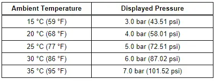
- Measure the ambient temperature (must be warmer than 15 ºC (59 ºF) ).
- Close the doors, the engine hood, the windows, the sliding sunroof and the rear lid.
- Open all instrument panel vents, the B-pillar vents, and the vents in the rear center console.
- Start the engine.
- Switch off the A/C compressor ("ECON" mode set on the Front A/C Display Control Head -E87- the indicator lamp in the A/C and the A/C MAX buttons do not turn on).
- Initiate the A/C system Guided Fault Finding. Refer to Vehicle Diagnostic Tester.
- Select the measured values for the activation of the A/C compressor and the pressure in the coolant circuit and read out the measured values in the "read measured values" function. Refer to Vehicle Diagnostic Tester in the "Guided Fault Finding" function.
 Note
Note
For the following test, various measured values can be selected in Guided Fault Finding and displayed in a table. Refer to Vehicle Diagnostic Tester in the "Guided Fault Finding" function.
For the cooling output test, it is helpful to display the following measured values of the Front A/C Display Control Head -E87-:
 Note
Note
Depending on vehicle equipment, there are different versions of the A/C system for the Audi Q7. Make sure to use the correct version and pay attention to the allocation of different components. Refer to → Chapter "A/C System Versions" and Parts Catalog.
- The measured values of the following temperature sensors (Evaporator Vent Temperature Sensor -G263-, Left Front Upper Body Vent Temperature Sensor -G385-, Right Front Upper Body Vent Temperature Sensor -G386-, Left Footwell Vent Temperature Sensor -G261-, Right Footwell Vent Temperature Sensor -G262-).
- The measured value of the Rear Upper Body Vent Temperature Sensor -G537- (only installed for a vehicle with a "Low"Mid" or "Mix" A/C system, a rear air distribution housing, without and with a Rear A/C Display Control Head -E265- version -A-).
- The request or the activation of the following components (Fresh Air Blower -V2-, Rear Fresh Air Blower -V80-, Radiator Fan -V7-, Radiator Fan 2 -V177-).
- The request or the activation of the following components (if equipped, depending on the equipment and engine type Coolant Recirculation Pump -V50-/Recirculation Pump -V55-, Coolant Shut-Off Valve -N82-/Heater Coolant Shut-Off Valve -N279-).
- The request or activation of the A/C Compressor Regulator Valve -N280- (compressor shut-off conditions and actual compressor current)
- The coolant temperature and the ambient temperature.
- The measured value for the High Pressure Sensor -G65- (refrigerant pressure).

Checking
- The A/C compressor is switched off. A current of 0 A (amps) for the activation of the A/C Compressor Regulator Valve -N280- is displayed.
- The refrigerant circuit pressure is same at the measured ambient temperature or is greater than the value in the table.
 Note
Note
- At absolute pressure, 0 bar corresponds to absolute vacuum. Normal ambient pressure equals approximately 1 bar (14.5 psi) absolute pressure and 0 bar pressure. On the scales of most pressure gauges, 0 bar pressure corresponds to an absolute pressure of one bar (can be seen from -1 mark below 0).
- Depending on the version of the Front A/C Display Control Head -E87-, only integer values may be displayed as measured values. If the measured pressure is between two values, the display alternates between the two values.
- Pressure in refrigerant circuit is governed by the ambient temperature. On account of heat given off by components (for example, the radiator), pressure displayed with warm engine will be slightly higher than that given for the respective ambient temperature.
- If pressure displayed is below that indicated in table. Check the signal of the High Pressure Sensor -G65-. Refer to Vehicle Diagnostic Tester in the "Guided Fault Finding" function. If no fault can be determined at the High Pressure Sensor -G65-, there is insufficient refrigerant in the circuit. Bring the vehicle to a workshop that has the necessary tools and where the work can be performed accordingly by qualified personnel. Refer to → Refrigerant R134a Servicing; Rep. Gr.87; A/C System, General Information.
The Refrigerant Circuit Pressure is OK
- Switch the A/C compressor on by selecting the "Auto" mode on the Front A/C Display Control Head -E87- front A/C display control head (the indicator lamps in the AUTO buttons and the A/C MAX button illuminates).
 Note
Note
By selecting the SYNC function on the Front A/C Display Control Head -E87- on vehicles with a "High" A/C system the settings of the front driver side are transferred to the front passenger side and also the Version -B-Rear A/C Display Control Head -E265-.
- Via the rotary switch(es) of the Front A/C Display Control Head -E87-, the temperature preselection is set to "cold" (for the driver and front passenger side).
- On vehicles with a "Mid" or "Mix" A/C system on the Rear A/C Display Control Head -E265- adjust the temperature preset for the rear to "cold".
- On vehicles with a "High" A/C system on the Rear A/C Display Control Head -E265- adjust the temperature preset for the left and right rear side to "cold".
- Via the rotary switches or buttons on the Front A/C Display Control Head -E87-, set the air flow direction to the "instrument panel vents" (for the driver and front passenger side).
- In vehicles with a "High" A/C system on the Rear A/C Display Control Head -E265-, set the air flow direction via the rotary switches on the Rear A/C Display Control Head -E265- (version -B-) to the vents in the rear center console.
 Note
Note
- The indicator lamp in the AUTO button goes out when performing manual changes for the airflow direction and/or the fresh air blower speed.
- The maximum possible fresh air blower speed depends on several conditions (coolant temperature, vehicle voltage, etc.)
- In the "read measured values" for the Front A/C Display Control Head -E87-, read the actual current with which the A/C Compressor Regulator Valve -N280- is activated (if the actual current is greater than 0.3 A, then the A/C compressor is switched on). Refer to Vehicle Diagnostic Tester in the "Guided Fault Finding" function.
 Note
Note
- The target current is calculated by the Front A/C Display Control Head -E87-. The request is sent via the data bus to the Vehicle Electrical System Control Module -J519- and the -J519- activates the A/C Compressor regulator Valve -N280- and reports the actual current. Refer to Vehicle Diagnostic Tester in the "Guided Fault Finding" function.
- If no or very little current is displayed as the measured value, check the activation of the A/C Compressor Regulator Valve -N280-. Refer to → Chapter "A/C Compressor Regulator Valve -N280-, Checking Switch-On Signal".
- Activation of the A/C Compressor Regulator Valve -N280- is performed by the Front A/C Display Control Head -E87- via the Vehicle Electrical System Control Module -J519-. The activation of the A/C Compressor Regulator Valve -N280- is displayed as the measured value in the Vehicle Electrical System Control Module -J519-. Refer to Vehicle Diagnostic Tester in the "Guided Fault Finding " function.
- The actual current flowing through the A/C Compressor Regulator Valve -N280- is measured by the Vehicle Electrical System Control Module -J519- and is sent via the data bus to the Front A/C Display Control Head -E87-. Refer to Vehicle Diagnostic Tester in the "Guided Fault Finding" function.
- In the "read measured values" function, read out the refrigerant circuit pressure measured by the refrigerant High Pressure Sensor -G65-. The displayed pressure goes over the value for a A/C compressor that is switched off. Refer to Vehicle Diagnostic Tester in the "Guided Fault Finding" Function.
 Note
Note
- The pressure displayed in the displayed measured value does not change and the A/C compressor activation is OK. Refer to Vehicle Diagnostic Tester in the "Guided Fault Finding" function. Check again whether the A/C compressor is actually driven and the A/C Compressor Regulator Valve -N280- is activated. If the A/C compressor is being driven and the A/C Compressor regulator valve -N280- is activated, there is a malfunction in the refrigerant circuit. Bring the vehicle to a workshop that has the necessary tools and where the work can be performed accordingly by qualified personnel. Refer to → Refrigerant R134a Servicing; Rep. Gr.87; A/C System, General Information. If the A/C compressor control is not OK, then inform the workshop of the problem at hand.
- The A/C Compressor Regulator Valve -N280- is activated by the Front A/C Display Control Head -E87- (via the Vehicle Electrical System Control Module -J519-) so that the temperature of the air downstream from the evaporator reaches the specified value (approximately 2 to 5 ºC (35.6 to 41 ºF) ).
- After starting the vehicle, a value greater than 0.55 A is displayed for the activation of the A/C Compressor Regulator Valve -N280- depending on the measured temperature, the engine speed and the electrical system voltage. As soon as the temperature measured by the Evaporator Vent Temperature Sensor -G263- approaches the specified value, activation is canceled and the compressor output is thus reduced.
- Under certain operating conditions, moisture in the refrigerant circuit can lead to ice build-up on the A/C Compressor Regulator Valve -N280- (and on the expansion valve). This ice build-up interferes with A/C compressor regulation. The evaporator is cooled too intensely and freezes. The freeze-up of the evaporator can be the cause for various customer complaints. Refer to → Chapter "Localizing Malfunction for Ice Build-Up on Evaporator".
- Push the button for the recirculating air mode on the Front A/C Display Control Head -E87- (the symbol for "recirculating air mode" in the recirculation button turns on).
- Set engine speed of 2000 rpm (start of time measurement).
- In the "read measured values" function, read out the measured value of the Evaporator Vent Temperature Sensor -G263-. Refer to Vehicle Diagnostic Tester in the "Guided Fault Finding" function.
- Use a thermometer to measure the temperature of the air from the vent in the rear center console.
- Compare the displayed value (for the Evaporator Vent Temperature Sensor -G263-) with the values in the diagram.
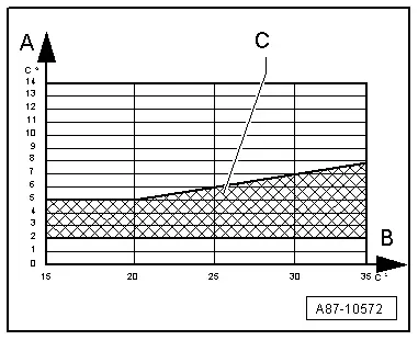
A - Air temperature measured by the Evaporator Vent Temperature Sensor -G263- (after evaporator in the front heater and A/C unit)
B - Ambient temperature
C - Permissible tolerance range
 Note
Note
Depending on vehicle equipment, there are different versions of the A/C system for the Audi Q7. Make sure to use the correct version and pay attention to the allocation of different components. Refer to → Chapter "A/C System Versions" and Parts Catalog.
- Depending on the ambient temperature, the measured air temperature after the front evaporator (measured value of the Evaporator Vent Temperature Sensor -G263-) must be within stated tolerance range -C- after five minutes.
- The measured temperatures from the vents of the rear center console correspond to the temperature measured by the Evaporator Vent Temperature Sensor -G263-. Permitted variance to the measured value of the front Evaporator Vent Temperature Sensor -G263- maximum + 9 ºC (48.2 ºF) (on a vehicle with a "Low"Mid" or "Mix" A/C system with or without a Rear A/C Display Control Head -E265- the version -A- and + 6 ºC /- 3 ºC (42.8 ºF/26.6 ºF) for a vehicle with a "High" A/C system (a rear heater and A/C unit and a version -B-Rear A/C Display Control Head -E265-) but not lower than +1 ºC (33.8 ºF).
 Note
Note
- If the required values for the front are not reached, check the measured value of the Evaporator Vent Temperature Sensor -G263-. Additionally compare the displayed measured value of the Sensor Evaporator Vent Temperature -G263- with the measured values of the Left Front Upper Body Vent Temperature Sensor -G385- and Right Front Upper Body Vent Temperature Sensor -G386- with each other.
- If the measured value of the Evaporator Vent Temperature Sensor -G263- only slightly deviates from the measured value for the Left Front Upper Body Vent Temperature Sensor -G385- and the Right Front Upper Body Vent Temperature Sensor -G386-. Determine the malfunction when there is a deviation from specified value. Refer to → Chapter "Malfunction Determination in Case of Deviation from Target Value (Required Cooling Output of Front A/C System not Achieved)".
- If the measured value of the Evaporator Vent Temperature Sensor -G263- is greater than the measured value of the Left Front Upper Body Vent Temperature Sensor -G385- or the Right Front Upper Body Vent Temperature Sensor -G386-, check the Evaporator Vent Temperature Sensor -G263- for proper installation (refer to → Chapter "Evaporator Vent Temperature Sensor -G263-, Removing and Installing") and perform an electrical test for this sensor. Refer to Vehicle Diagnostic Tester in the "Guided Fault Finding" function.
- The A/C system function can be recognized, for example, when the refrigerant line "low pressure side" (wide line in the plenum chamber between the expansion valve and the refrigerant line with the inner heat exchanger under the left fender) cools down and the refrigerant line "high pressure side" (narrow line between the inner heater core and the expansion valve) warms up. Refer to → Chapter "System Overview - Refrigerant Circuit with Rear Heater and A/C Unit".
- If the deviation of the rear measured value from the front measured value is too great. Refer to → Chapter "Malfunction Determination if Cooling Output of Front A/C System is OK but Required Values not Achieved in Rear".
If the measured value of the Evaporator Vent Temperature Sensor -G263- (and thus the cooling output of the front A/C system) is OK and if there is no complaint, the cooling output test ends.
- If the measured value of the Evaporator Vent Temperature Sensor -G263- (and thus the cooling output of the A/C system) is not OK, determine the malfunction causing the deviation from the target value (the required cooling output is not reached). Refer to → Chapter "Malfunction Determination in Case of Deviation from Target Value (Required Cooling Output of Front A/C System not Achieved)".
- If the measured value of the Evaporator Vent Temperature Sensor -G263- (and thus the front A/C system cooling output) is OK and if there is a complaint that the front A/C system vent temperatures are too high or differ, check the activation of the temperature doors in the front heater and A/C unit. Refer to → Chapter "Heat Output and Temperature Door Activation, Checking".

- If the measured value of the Evaporator Vent Temperature Sensor -G263- (and thus the front A/C cooling output) is OK and if there is a complaint that the rear vent temperatures are too high or differ in vehicles with a "High" A/C system (with a version -B-Rear A/C Display Control Head -E265-, check rear A/C cooling output. Refer to → Chapter "Malfunction Determination if Cooling Output of Front A/C System is OK but Required Values not Achieved in Rear".
- If the measured value of the Evaporator Vent Temperature Sensor -G263- (and thus the front A/C cooling output) is OK, and there is a concern about the cooling output from the rear vents (excessive or different temperatures of the air from the rear vents), on vehicles with a "Low"Mid" or "Mix" A/C cooling output (with our without version -A-Rear A/C Display Control Head -E265-), check the activation of the temperature control doors in the front heater and A/C unit. Refer to → Chapter "Heat Output and Temperature Door Activation, Checking".
- If the measured value of the Evaporator Vent Temperature Sensor -G263- (and thus the front A/C cooling output) is OK, and there is a complaint that the temperature of the air from the rear vents is too low or there is a lack of air from the rear vents after a while in vehicles with a "High" A/C system (with a version -B-Rear A/C Display Control Head -E265-), check the cooling output of the rear A/C system. Refer to → Chapter "Malfunction Determination if Cooling Output of Front A/C System is OK but Required Values not Achieved in Rear".


