Audi Q7: Crankcase Ventilation
Overview - Crankcase Ventilation
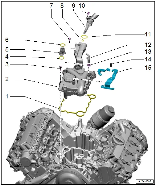
1 - Seal
- Replace after removing
2 - Oil Separator with Cover
- With connection for crankcase ventilation
- Removing and installing. Refer to → Chapter "Oil Separator, Removing and Installing".
3 - Bolt
- 9 Nm
4 - O-Ring
- Replace after removing
- Market-specific North America (quantity: 2)
5 - Connection
- For the crankcase ventilation
- Installation position. Refer to → Fig. "Crankcase Ventilation Connection, Installing".
6 - O-Ring
- Replace after removing
- Market-specific North America (quantity: 2)
7 - Bolt
- 9 Nm
8 - O-Ring
- Replace after removing
9 - Crankcase Ventilation Hose
- To the cylinder head covers
- Removing and installing. Refer to → Chapter "Crankcase Ventilation Hose, Removing and Installing".
10 - Bolt
- 2.5 Nm
11 - O-Ring
- Replace after removing
12 - Crankcase Ventilation Hose
- To the air duct pipe
- With Crankcase Ventilation Shut-Off Valve -N548-
13 - Hose Clamp
14 - Bolt
- 2.5 Nm
15 - Bracket
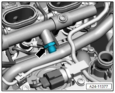
Crankcase Ventilation Connection, Installing
- Insert the crankcase ventilation connection -1- with new O-rings into the oil separator cover.
- Installation position: the tab -2- must engage into the guide -arrow-.
Oil Separator, Removing and Installing
 Caution
This procedure contains mandatory replaceable parts. Refer to component overview prior to starting procedure.
Mandatory Replacement Parts
- Seal - Oil separator with cover
- O-rings - Crankcase ventilation hose
Removing
- Remove the high pressure pipe. Refer to → Chapter "High Pressure Pipe, Removing and Installing".
- Remove the upper coolant pipe. Refer to → Chapter "Upper Coolant Pipe, Removing and Installing".
- Remove the Fuel Pressure Sensor -G247-. Refer to → Chapter "Fuel Pressure Sensor -G247-, Removing and Installing".
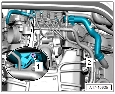
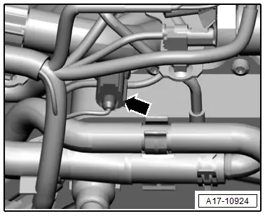
- Remove the left and right connection -arrow-.
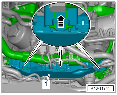
- Remove the bolt -1-.
- Remove the connection with the crankcase ventilation hose.
 Note
Note
- The illustration shows the installation position with the compressor installed.
- Ignore -2-.
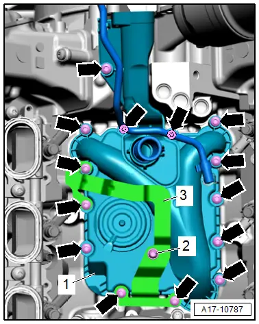
- Remove the bolts -2 and arrows-.
- Remove the bracket -3-.
- Push the wire and vacuum hoses to the side and remove the oil separator with cover -1-.
Installing
Install in reverse order of removal and note the following:
 Note
Note
- Replace the seal and O-ring after removal.
- Replace the connection -arrow-.
- Install the Fuel Pressure Sensor -G247-. Refer to → Chapter "Fuel Pressure Sensor -G247-, Removing and Installing".
- Install the upper coolant pipe. Refer to → Chapter "Upper Coolant Pipe, Removing and Installing".
- Install the high pressure pipe. Refer to → Chapter "High Pressure Pipe, Removing and Installing".

Tightening Specifications
- Refer to → Chapter "Overview - Crankcase Ventilation"
- Refer to → Chapter "Overview - Fuel Rail with Fuel Injectors"
Crankcase Ventilation Hose, Removing and Installing
 Caution
This procedure contains mandatory replaceable parts. Refer to component overview prior to starting procedure.
Mandatory Replacement Parts
- O-rings - Crankcase ventilation hose
Removing
 Note
Note
- During installation, all cable ties must be installed at the same location.
- The crankcase ventilation hose cannot be remove from the left cylinder head cover without damaging it. The hose must be replaced after removal.
- Remove the Throttle Valve Control Module -J338-. Refer to → Chapter "Throttle Valve Control Module -J338-, Removing and Installing".
- Disconnect the connectors -1 through 4-.
 Note
Note
Ignore -5-.
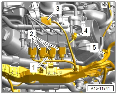
- Disconnect the connector -arrow- for the Oil Pressure Switch -F22- and free up the wire.
- Free up the wiring harness.
- Release the retainers in direction of -arrow- and remove wiring duct -1- toward the rear.
- Push the wiring duct downward.
- Remove the crankcase ventilation hose -2- from the cylinder head covers.
- Free up the crankcase ventilation hose.
- Remove the bolt -1- and the connection for the crankcase ventilation hose.

Installing
Install in reverse order of removal and note the following:
 Note
Note
Replace the O-rings after removing them.
- Connections and wire routing. Refer to → Wiring diagrams, Troubleshooting & Component locations.
- Install the Throttle Valve Control Module -J338-. Refer to → Chapter "Throttle Valve Control Module -J338-, Removing and Installing".
Tightening Specifications
- Refer to → Chapter "Overview - Crankcase Ventilation"

