Audi Q7: Oil Filter/Oil Pressure Switch
Overview - Oil Filter
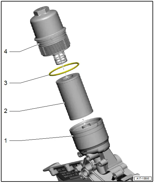
1 - Oil Filter Housing
- With filter bypass valve
- With oil drain valve
- One unit with the lower timing chain cover
2 - Oil Filter Element
- Removing and installing.
3 - Gasket
4 - Cap
- 25 Nm
Overview - Oil Pressure Switch/Oil Pressure Regulation Valve
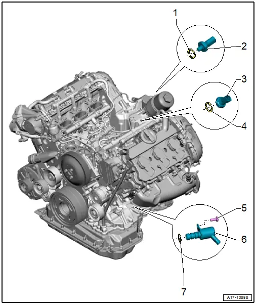
1 - Gasket
- Replace after removing
2 - Oil Pressure Switch -F22-
- 20 Nm
- Switching pressure 2.5 to 3.2 bar (36.25 to 46.41 psi) (oil pump high pressure side)
- Black insulation
- Checking using Vehicle Diagnostic Tester.
- Removing and installing. Refer to → Chapter "Oil Pressure Switch -F22-, Removing and Installing".
3 - Reduced Oil Pressure Switch -F378-
- 20 Nm
- Switching pressure 0.75 to 1.05 bar (10.87 to 15.22 psi) (oil pump low pressure side)
- Light gray insulation
- Checking using Vehicle Diagnostic Tester.
- Removing and installing. Refer to → Chapter "Reduced Oil Pressure Switch -F378-, Removing and Installing".
4 - Gasket
- Replace after removing
5 - Bolt
- 9 Nm
6 - Oil Pressure Regulation Valve -N428-
- Checking using the Vehicle Diagnostic Tester.
- Removing and installing. Refer to → Chapter "Oil Pressure Regulation Valve -N428-, Removing and Installing".
7 - O-Ring
- Replace after removing
Oil Pressure Switch -F22-, Removing and Installing
Special tools and workshop equipment required
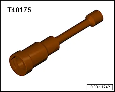
- Socket and Jointed Extension - 24mm -T40175-
 Caution
This procedure contains mandatory replaceable parts. Refer to component overview prior to starting procedure.
Mandatory Replacement Parts
- Gasket - Oil pressure switch
Removing
- Remove the air filter housing. Refer to → Chapter "Air Filter Housing, Removing and Installing".
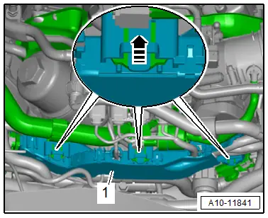
- Release the catches in direction of -arrow-, remove the wiring duct -1- toward the rear and push it slightly upward.
- Free up the wire and hoses and push to the side.
 Note
Note
To collect escaping engine oil, place a clean cloth under oil filter housing.
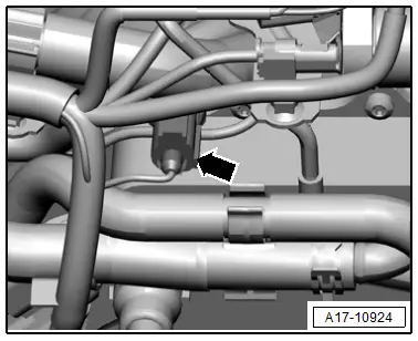
- Disconnect the connector -arrow-.
- Remove the Oil Pressure Switch -F22- using the Socket and Jointed Extension - 24mm -T40175-.
Installing
Install in reverse order of removal and note the following:
 Note
Note
- Replace the gasket after removal.
- To prevent engine oil loss, insert the new Oil Pressure Switch -F22- into the hole immediately.
- Install the air filter housing. Refer to → Chapter "Air Filter Housing, Removing and Installing".
- Check the oil level.
Tightening Specifications
- Refer to → Chapter "Overview - Oil Pressure Switch/Oil Pressure Regulation Valve"
Reduced Oil Pressure Switch -F378-, Removing and Installing
Special tools and workshop equipment required
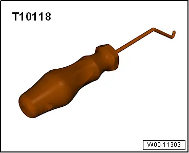
- Elbow Assembly Tool -T10118-
- Socket and Jointed Extension - 24mm -T40175-
 Caution
This procedure contains mandatory replaceable parts. Refer to component overview prior to starting procedure.
Mandatory Replacement Parts
- Gasket - Reduced oil pressure switch
Removing
- Remove the supercharger. Refer to → Chapter "Supercharger, Removing and Installing".
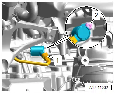
- Disconnect the electrical connector -2- using the Elbow Assembly Tool -T10118-.
- Remove the Reduced Oil Pressure Switch -F378--1- with a Socket and Jointed Extension - 24mm -T40175-.
Installing
Install in reverse order of removal and note the following:
 Note
Note
Replace the gasket after removal.
- Install the supercharger. Refer to → Chapter "Supercharger, Removing and Installing".
Tightening Specifications
- Refer to → Chapter "Overview - Oil Pressure Switch/Oil Pressure Regulation Valve"
Oil Pressure, Checking
Special tools and workshop equipment required
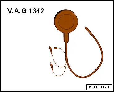
- Oil Pressure Gauge Kit -VAG1342-
 Caution
This procedure contains mandatory replaceable parts. Refer to component overview prior to starting procedure.
Mandatory Replacement Parts
- Gasket - Oil pressure switch
Procedure
- Oil level OK
- Engine oil temperature approximately 80 ºC (176 ºF)
- Remove the Oil Pressure Switch -F22-. Refer to → Chapter "Oil Pressure Switch -F22-, Removing and Installing".
- Connect the Oil Pressure Gauge Kit -VAG1342- in the opening for the oil pressure switch.
- Install the Oil Pressure Switch -F22- in the oil pressure tester.
- Start the engine.
- Oil pressure when the vehicle is idling is minimum 1.2 bar (17.4 psi).
- Oil pressure at 2,000 RPM is minimum 1.5 bar (21.75 psi).
Assembling
- Install the Oil Pressure Switch -F22-. Refer to → Chapter "Oil Pressure Switch -F22-, Removing and Installing".
Oil Pressure Regulation Valve -N428-, Removing and Installing
 Caution
This procedure contains mandatory replaceable parts. Refer to component overview prior to starting procedure.
Mandatory Replacement Parts
- O-ring - Oil pressure regulation valve
Removing
- Remove the front noise insulation. Refer to → Body Exterior; Rep. Gr.66; Noise Insulation; Noise Insulation, Removing and Installing.
- Remove the ribbed belt from the A/C compressor. Refer to → Chapter "Ribbed Belt, Removing and Installing, Sub-Assembly Ribbed Belt".
- Remove the A/C compressor from the bracket and tie it up toward the front. Refer to → Heating, Ventilation and Air Conditioning; Rep. Gr.87; A/C Compressor; A/C Compressor, Removing and Installing at Bracket.
- Remove the left subframe shield and push it slightly to the side. Refer to → Suspension, Wheels, Steering; Rep. Gr.40; Subframe; Subframe Shield, Removing and Installing.
- Disconnect the connector -1-.
 Note
Note
Lay a cloth below to catch the draining engine oil.
- Remove the bolt -2-, and remove the Oil Pressure Regulation Valve -N428-.
Installing
Install in reverse order of removal and note the following:
 Note
Note
Replace the O-ring after removing.
- Install the ribbed belt. Refer to → Chapter "Ribbed Belt, Removing and Installing, Sub-Assembly Ribbed Belt".
Tightening Specifications
- Refer to → Chapter "Overview - Oil Pressure Switch/Oil Pressure Regulation Valve"
- Refer to → Suspension, Wheels, Steering; Rep. Gr.40; Subframe; Overview - Subframe.
- Refer to → Heating, Ventilation and Air Conditioning; Rep. Gr.87; A/C Compressor; Overview - A/C Compressor Power Unit.
- Refer to → Body Exterior; Rep. Gr.66; Noise Insulation; Overview - Noise Insulation.
Special Tools
Special tools and workshop equipment required
- Elbow Assembly Tool -T10118-
- Socket and Jointed Extension - 24mm -T40175-
- Oil Pressure Gauge Kit -VAG1342-
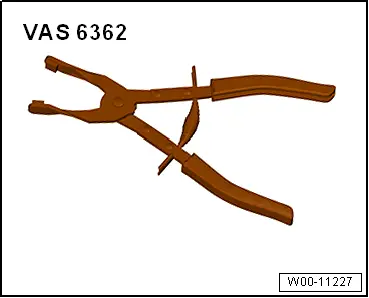
- Hose Clip Pliers -VAS6362-