Audi Q7: CV Joint, Servicing
Outer CV Joint, Removing
- Clamp the drive axle in a vise with protective covers.
- Open both clamping sleeves and remove protective joint boot from outer joint.
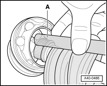
- Drive out the CV joint from the drive axle with a copper or brass mandrel -A- on the inner ring.
- Remove joint and protective joint boot.
Outer CV Joint, Installing
- Joints and protective joint boots must be free of grease.
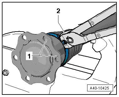
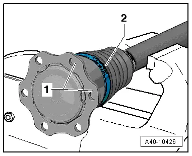
- Replace the circlip -1- after removing.
- Slide on the small clamp with the CV boot.
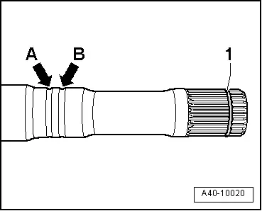
- Position the CV boot on the outer groove -arrow B-.
- Inner groove -arrow A- remains visible "identification groove" (for correct installation of CV boot).
- Add the specified quantity of grease to the inside of the joint.
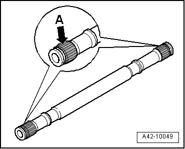
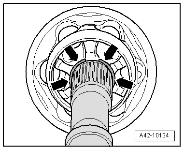
- Before installing joint, splines -arrow A- must be lightly coated with grease used in joint.
- Insert sealing ring in groove on shaft.
- Slide on CV joint up to sealing ring.
- Align sealing ring at center with opening upward -arrows-.
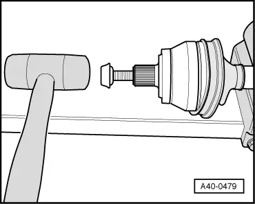
- Install the old drive axle bolt in the joint.
- Drive joint onto the drive axle with a plastic hammer until the circlip engages.
- Add the specified quantity of the grease into the joint on the CV boot side.
- Slide the protective boot onto the joint.
- Bleed the CV boot.
- Make sure the protective boot is seated on the joint correctly.
- The CV boot must fit in the groove and on joint contour.
- Tension the clamps on outer joint. Refer to → Chapter "Clamp on Triple Roller Joint and Outer Joint, Tensioning".
Outer CV Joint, Checking
It is necessary to disassemble the joint whenever replacing the grease or if the ball surfaces show wear or damage.
Disassembling
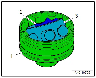
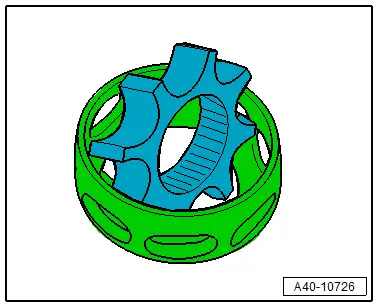
- Mark position of ball hub -2- to ball cage -3- and to housing -1- before disassembling, using an electric engraver or grindstone.
- Swivel the ball hub and ball cage.
- Remove the balls one after the other.
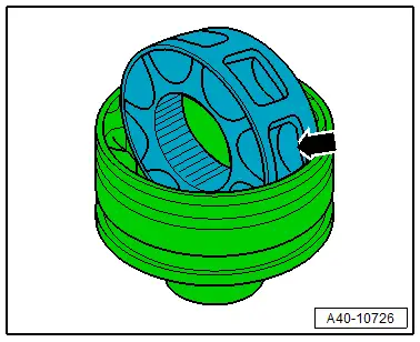
- Turn cage, until two rectangular windows -arrow- contact joint body.
- Lift out cage with hub.
- Swing hub segment with smaller pins into rectangular window on cage.
- Fold hub out from cage.
Checking
The balls of each joint belong to one tolerance group. Check stub axle, hub, cage and balls for small depressions (pitting build-up) and chafing. Excessive backlash in the joint is noticeable by a thump during load alternations. The joint should be replaced in these cases. Flattening and running marks on the balls are no reason to replace a joint.
Assembling
- Insert cage with hub into joint body.
 Note
Note
Cage must be installed laterally correct.
- Press in the opposite facing balls one after the other, and the old position of the ball hub bearing to the ball cage and to the joint housing must be replicated.
- Press the grease into the joint body.
Clamp on Triple Roller Joint and Outer Joint, Tensioning
Special tools and workshop equipment required
- Torque Wrench 1331 5-50Nm -VAG1331-
- Clampling Pliers -VAG1682A-
- Locking Pliers -VAS6199-
 Note
Note
Depending on the version of the clamp, use the following tools:
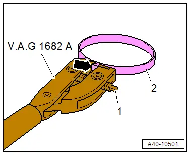
Tension the Stainless Steel Clamp Using the Clampling Pliers -VAG1682A-.
- Attach the Clampling Pliers -VAG1682A- as shown.
- The jaws on the pliers must be centered -arrow- on the clamp -2-.
 Note
Note
- The spindle threads must turn easily. If necessary, coat with MoS2 lubricating grease.
- If difficult to tighten, for example because of dirty threads, the proper clamping force of the clamping sleeve will not be reached even when tightened to the specification.
- Tension the clamp by turning the spindle -1- with the torque wrench, at the same time do not tilt the clamping pliers.
- Tightening specification: 20 Nm.
Tension the Clamp with Retaining Tabs Using the Locking Pliers -VAS6199-.
 Note
Note
For a better position of multi-point socket head bolts when installing drive axle, clamping sleeve connecting tube -2- must be between joint connecting flanges -1-.
- Engage the clamp at the first catch by hand.
- Close the clamp using the Locking Pliers -VAS6199--2-.