Audi Q7: Disposal
Front Gas-Filled Shock Absorbers, Venting and Draining
Special tools and workshop equipment required
- Hand drill
- 3 mm diameter drill bit.
- 6 mm diameter drill bit
- Oil collecting container
- Protective Eyewear
Procedure
- Secure gas-filled shock absorber vertically in vise, with piston rod facing down.
 WARNING
Risk of eye injury.
Wear protective eyewear!
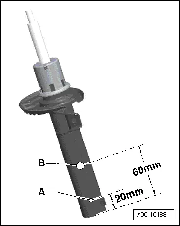
- Drill a 3 mm hole -A- through the shock absorber outer tube.
 Note
Note
Gas escapes when drilling.
- Continue drilling until the tube inside is drilled through (approximately 25 mm deep).
- Drill a second 6 mm hole -B- through the outer and inner shock absorber tubes.
- Hold the shock absorber over an appropriate container for catching oil and move the piston rod repeatedly through the entire stroke until no more oil flows out.
Rear Gas-Filled Shock Absorbers, Venting and Draining
Special tools and workshop equipment required
- Hand drill
- 3 mm diameter drill bit.
- 6 mm diameter drill bit
- Oil collecting container
- Protective Eyewear
Procedure
- Secure the gas-filled shock absorber vertically in vise, with piston rod facing down.
 WARNING
Risk of eye injury.
Wear protective eyewear!
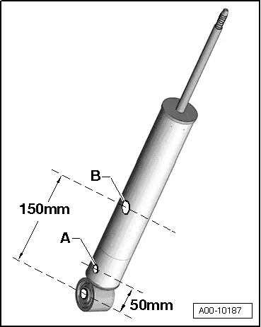
- Drill a 3 mm hole -A- through the shock absorber outer tube.
 Note
Note
Gas escapes when drilling.
- Continue drilling until the tube inside is drilled through (approximately 25 mm deep).
- Drill a second 6 mm hole -B- through the outer and inner shock absorber tubes.
- Hold the shock absorber over an appropriate container for catching oil and move the piston rod repeatedly through the entire stroke until no more oil flows out.
Front Air Suspension Strut, Emptying
Procedure
- Remove the air spring: front. Refer to → Chapter "Suspension Strut, Removing and Installing"; rear. Refer to → Chapter "Shock Absorber, Removing and Installing".
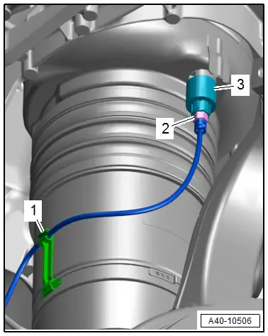
- Release from the residual pressure retaining valve air spring -3- and allow the air pressure to escape.
- Dispose of the air spring.
 Note
Note
- The front air spring is shown installed.
- Ignore -1 and 2-.
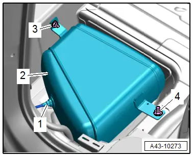
Pressure Reservoir, Emptying
Procedure
- Connect the Vehicle Diagnostic Tester.
- Switch the ignition on.
- Select and start the Diagnostic operating mode.
- Select the Test plan tab.
- Select the button Individual tests and select the following tree structures one after the other:
- Suspension
- Suspension control
- 01 - OBD-capable systems
- 74 - Drivetrain Control Module J775
- 74 - Drivetrain Control Module Functions
- 74 - Complete basic setting
- Start the selected program and follow the instructions in the display of the Vehicle Diagnostic Tester.
- Slowly loosen air line -1- on pressure reservoir -2- and allow air pressure to come down. After the air pressure has escaped, remove the air line.
- Remove and dispose of the pressure reservoir. Refer to → Chapter "Pressure Reservoir, Removing and Installing".
 Note
Note
Ignore -3 and 4-.
Special Tools
Special tools and workshop equipment required
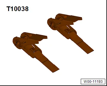
- Tensioning Strap -T10038-
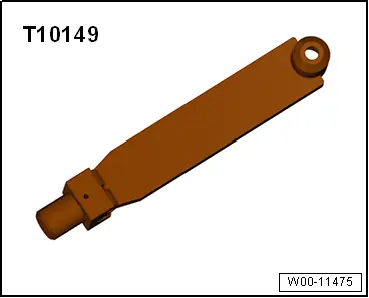
- Engine/Gearbox Jack Adapter - Wheel Hub Support -T10149-
- Engine and Gearbox Jack -VAS6931-