Audi Q7: Overview - Subframe
Audi Q7 (4M) 2016-2026 Workshop Manual / Chassis / Suspension, Wheels, Steering / Front Suspension / Overview - Subframe
Subframe
 Caution
There is a risk of damaging the threads on the subframe threaded connection to the body.
- The subframe bolts on the body must not be loosened or tightened with an impact wrench.
- Always install all bolts by hand for the first few turns.
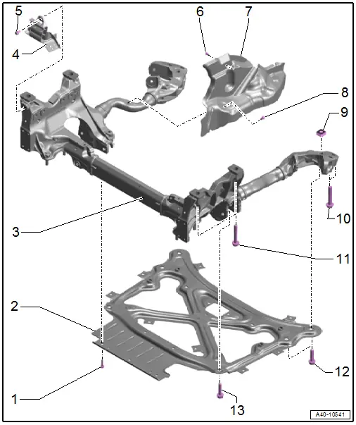
1 - Bolt
- 20 Nm
2 - Subframe Crossbrace
- Removing and installing. Refer to → Chapter "Subframe Crossbrace, Removing and Installing".
 Caution
There is a risk of damaging the suspension components.
- If the subframe mount, steering gear or subframe crossbrace are not installed correctly, do not rest the vehicle on its wheels.
- Supporting the vehicle at the subframe or the subframe crossbrace (for example, using a floor jack or similar device) is not permitted.
3 - Subframe
- Securing. Refer to → Chapter "Subframe, Securing".
- Lowering. Refer to → Chapter "Subframe, Lowering".
- Removing and installing. Refer to → Chapter "Subframe with Steering Gear, Removing and Installing".
 Note
Note
Perform a pre-adjustment on the subframe if it is being replaced or if it had to be removed in order to loosen the crossbrace. Refer to → Fig. "Pre-Adjustment of the Subframe:".
4 - Bracket
- For the electrical wiring harness
5 - Bolt
- 9 Nm
6 - Bolt
- 9 Nm
7 - Shield
- There are different versions. Refer to the Parts Catalog.
- Removing and installing. Refer to → Chapter "Subframe Shield, Removing and Installing".
8 - Bolt
- 9 Nm
9 - Square Nut
10 - Bolt
- 130 Nm +180º
- Replace after removing
- Remove and tighten together with -11- diagonally in steps
11 - Bolt
- 115 Nm +90º
- Replace after removing
- Remove and tighten together with -10- diagonally in steps
12 - Bolt
- 90 Nm +135º
- 42 mm long
- Replace after removing
13 - Bolt
- 90 Nm +90º
- Replace after removing
- 51 mm long
Stabilizer Bar
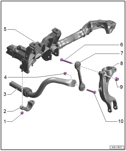
1 - Nut
- 50 Nm
- Replace after removing
- Remove and tighten evenly alternating from side to side.
2 - Clamp
3 - Stabilizer Bar
- With rubber bushing
- The rubber bushing cannot be replaced separately
- Removing and installing. Refer to → Chapter "Stabilizer Bar, Removing and Installing".
4 - Nut
- 40 Nm +90º
- Replace after removing
5 - Subframe
6 - Bolt
- Replace after removing
7 - Coupling Rod
- Removing and installing. Refer to → Chapter "Coupling Rod, Removing and Installing".
8 - Shock Absorber Fork
- Removing and installing. Refer to → Chapter "Shock Absorber Fork, Removing and Installing".
9 - Nut
- 40 Nm +90º
- Replace after removing
10 - Bolt
- Replace after removing

