Audi Q7: Subframe, Securing
Special tools and workshop equipment required
- Torque Wrench 1331 5-50Nm -VAG1331-
- Torque Wrench 1332 40-200Nm -VAG1332-
- Engine and Gearbox Jack -VAS6931-
- Gearbox Support -T40173-
- Locating Pins -T40327-, not shown
Procedure
 WARNING
There is a risk of an accident due to an unsecured engine/transmission subassembly!
For the following steps the engine must be supported in the installation position.
- Hold the engine in its installed position. Refer to → Rep. Gr.10; Subframe Mount; Engine, Supporting in Installation Position.
- Remove the front wheels. Refer to → Chapter "Wheels and Tires".
- Remove the noise insulations. Refer to → Body Exterior; Rep. Gr.66; Noise Insulation; Noise Insulation, Removing and Installing.
- Remove the left and right wheel housing liner sections. Refer to → Body Exterior; Rep. Gr.66; Wheel Housing Liner; Front Wheel Housing Liner, Removing and Installing.
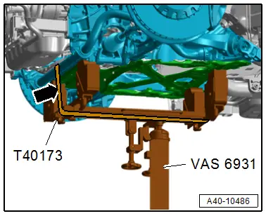
- Support the subframe with the Engine and Gearbox Jack - VAS6931- and the Gearbox Support -T40173- as shown.
- Secure the subframe with the tensioning strap -arrow-.
 Caution
There is a risk of damaging the threads on the subframe threaded connection to the body.
- The subframe bolts on the body must not be loosened or tightened with an impact wrench.
- Always install all bolts by hand for the first few turns.
 Note
Note
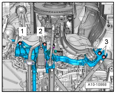
- To secure the subframe the Gearbox Support Locating Pins -T40327- must be installed one after the other on the left and right at the positions -1 and 2-.
- The locating pins must only be tightened to a maximum of 20 Nm or else the locating pin bolts will be damaged.
- Through the bolt washers the holes for the subframe are slightly peened. They must be deburred if necessary.
- Replace the bolts -1 and 2- one after the other on both sides of the vehicle via the Locating Pins -T40327- and tighten to 20 Nm.
- The suspension is now secured.
- Remove the left and right bolts -3-.
Remove the Locating Pins -T40327-
Removal is performed in the reverse order. Note the following:
- Only remove one bolt diagonally and install a new bolt in this location and tighten.
 Caution
There is a risk of damaging the threads on the subframe threaded connection to the body.
- The subframe bolts on the body must not be loosened or tightened with an impact wrench.
- Always install all bolts by hand for the first few turns.
 WARNING
Risk of accident!
If vehicle will be driving on the streets, all bolts and nuts must be tightened properly!
- Remove the Engine Support Bridge -10-222A-. Refer to → Rep. Gr.10; Subframe Mount; Engine, Supporting in Installation Position.
- A road test must be performed after completing repairs. If steering wheel is crooked, the wheels must be aligned. Refer to → Chapter "Vehicle Alignment".
Tightening Specifications
- Refer to → Chapter "Overview - Subframe"
- Refer to → Body Exterior; Rep. Gr.66; Wheel Housing Liner; Overview - Front Wheel Housing Liner.
- Refer to → Chapter "Wheels and Tires"
Subframe, Lowering
Special tools and workshop equipment required
- Torque Wrench 1331 5-50Nm -VAG1331-
- Torque Wrench 1332 40-200Nm -VAG1332-
Procedure
Before starting work:
- Versions with coil springs: determine the curb weight position. Refer to → Chapter "Wheel Bearing in Curb Weight Position, Lifting Vehicles with Coil Spring".
- Versions with air suspension: determine the standard vehicle height. Refer to → Chapter "Wheel Bearing at Standard Vehicle Height, Lifting Vehicles with Air Suspension".
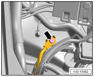
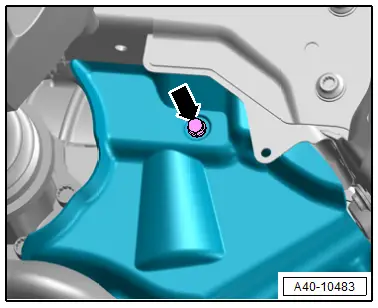
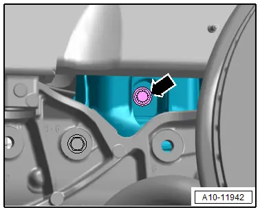
- Remove the bolt -arrow- and free up the ground wire.
- Secure the subframe. Refer to → Chapter "Subframe, Securing".
- Remove the front lower longitudinal member at the left and right. Refer to → Body Exterior; Rep. Gr.63; Front Bumper; Overview - Impact Member.
- Disconnect the left and right connector -3- from the vehicle level sensor and free up the wires.
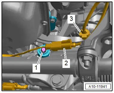
 Note
Note
Ignore -1 and 2-.
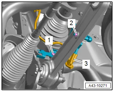
- Remove the bolt -2-.
- Disconnect the connector -3- and free up the wire.
- Remove the bolt -1-.
- Release the catches in direction of -arrows- and free up the bracket -4- for the wires from the subframe.
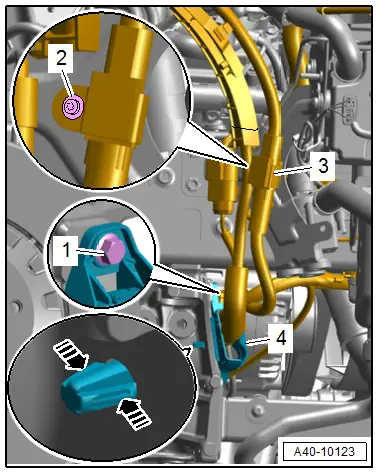
 Note
Note
The illustration shows the installation position on a vehicle without the parking heater.
- Free up the wire to the steering gear and to the stabilizer bar.
- Disconnect the left and right connector -3- for the electrohydraulic engine mount solenoid valve.
- Remove the connector -2- from the bracket, disconnect it and free up the wire.
- Equipment levels with support bearing: remove the left and right bolt -1- for the support bearing.
- Remove the left and right bolts -arrow- for the subframe shield.
- Remove the left and right nuts -3-.
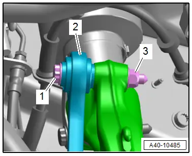
 Note
Note
The bolt -1- for the coupling rod -2- is removed later.
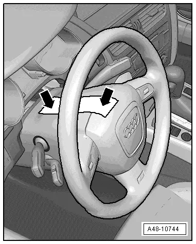
- Secure the steering wheel in the straight-ahead position using adhesive tape so that it does not turn -arrow-.
 Note
Note
- Use adhesive tape, that can be removed without leaving any adhesive residue.
- Be careful not to turn the steering wheel during the repair because the Airbag Spiral Spring/Return Spring with Slip Ring -F138- can become damaged.
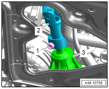
- Remove the bolt -1-.
- Remove the universal joint -2- from the steering gear -3-.
- Remove engine bracket left and right bolt -arrow-.
- Lower the subframe with the Engine and Gearbox Jack -VAS 6931- at the same time remove the left and right bolts for the coupling rod.
 Note
Note
Make sure there is enough clearance for the electric lines when lowering the subframe.
Installing
Install in reverse order of removal and note the following:
- Remove the Locating Pins -T40327-. Refer to → Chapter "Subframe, Securing".
- Install the steering intermediate shaft. Refer to → Chapter "Steering Intermediate Shaft, Removing and Installing".
 Note
Note
Bonded rubber bushings have a limited range of motion. Only tighten suspension bolts when vehicle is in curb weight position or at standard vehicle height.
- Lifting the wheel bearing in curb weight position (refer to → Chapter "Wheel Bearing in Curb Weight Position, Lifting Vehicles with Coil Spring") or at standard vehicle height (refer to → Chapter "Wheel Bearing at Standard Vehicle Height, Lifting Vehicles with Air Suspension").
 WARNING
Risk of accident!
If vehicle will be driving on the streets, all bolts and nuts must be tightened properly!
- Connections and wiring routing. Refer to → Wiring diagrams, Troubleshooting & Component locations.
Tightening Specifications
- Refer to → Chapter "Overview - Subframe"
- Refer to → Body Exterior; Rep. Gr.63; Front Bumper; Overview - Impact Member.
- Refer to → Body Exterior; Rep. Gr.66; Wheel Housing Liner; Overview - Front Wheel Housing Liner.
- Refer to → Chapter "Wheels and Tires"

