Audi Q7: Door Handle, Removing and Installing
Removing
- Remove the lock cylinder/housing. Refer to → Chapter "Lock Cylinder, Removing and Installing".
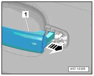
- Pull the door handle -1- in the direction of the -arrow-. This disengages the door handle from the operating lever in the mounting bracket.
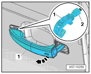
- Tilt the door handle -1- outward -arrow- and remove it from the mount on the mounting bracket.
- Equipped on some models: disconnect the connector -2- on the door handle.
- If the door handle is to be replaced, also remove the following components:
- Door handle trim. Refer to → Chapter "Door Handle Trim, Removing and Installing".
- Exterior door handle touch sensor. Refer to → Electrical Equipment; Rep. Gr.94; Access/Start Authorization Switch; Component Location Overview - Keyless Access Authorization System.
- Exterior door handle illumination. Refer to → Electrical Equipment; Rep. Gr.94; Exterior Door Handle Lamps; Exterior Door Handle Illumination Bulb, Removing and Installing.
Installing
Install in reverse order of removal and note the following:
 Note
Note
Replace the seals for the door handles if damaged or brittle.
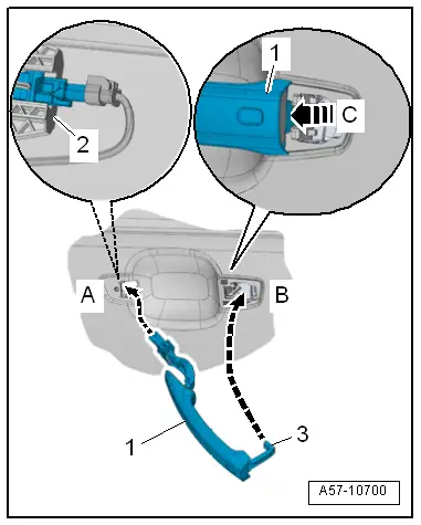
- Insert the door handle -1--arrow A-. It must engage in the mount -2- on the mounting bracket.
- Pivot the door handle in the direction of -arrow B- and engage audibly forward in the direction of travel -arrow C-.
- The carrier -3- is placed in the operating lever from this.
Door Handle Trim, Removing and Installing
Removing
- Remove the door handle. Refer to → Chapter "Door Handle, Removing and Installing".
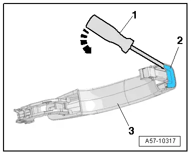
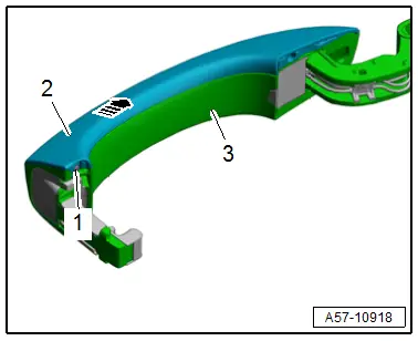
- Pry the door handle trim -2- out using an awl -1- at the location shown in the illustration -arrow-.
- Remove the trim from the door handle -3-.
Installing
Install in reverse order of removal.
Door Handle Trim Molding, Removing and Installing
Removing
- Remove the door handle. Refer to → Chapter "Door Handle, Removing and Installing".
- Remove the bolt -1-.
- Remove the trim molding -2- from the door handle -3--arrow-.
Installing
Install in reverse order of removal and note the following:
- The bolt head must not project over the contact surface for the tread.
Tightening Specifications
- Refer to → Chapter "Overview - Door Handle and Mounting Bracket".

