Audi Q7: Door Lock, Removing and Installing
 NOTICE
Risk of damaging the operating cable by deforming it.
- Never sharply bend or kink the operating cable.
Removing
- Remove the lock cylinder cover. Refer to → Chapter "Lock Cylinder Cap, Removing and Installing".
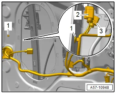
- Release the catches at the clip -1- and free up the wiring harness.
- Disconnect the connectors -2 and 3- on the door lock.
- Carefully remove the mounting bracket together with the door lock to the speaker opening out of the door.
- Disengage the operating cable from the operating lever on the mounting bracket. Refer to → Chapter "Door Lock Cable, Removing and Installing".
Installing
Install in reverse order of removal.
Tightening Specifications
- Refer to → Chapter "Overview - Door Handle and Door Lock"
Door Lock Cover, Removing and Installing
Removing
- Move the door window into the "closed" position.
- Remove the mounting bracket and place it toward the front. Refer to → Chapter "Mounting Bracket, Removing and Installing".
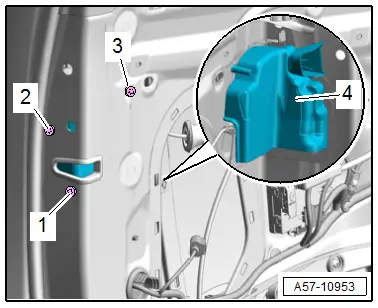
- Remove the bolts -1, 2 and 3- and move the door lock slightly to the side.
- Remove the guide -4- from the door lock.
Installing
Install in reverse order of removal.
Tightening Specifications
- Refer to → Chapter "Overview - Door Handle and Door Lock"
Striker, Removing and Installing
Removing
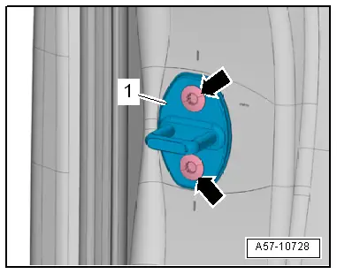
- Remove the bolts -arrows- and remove the striker -1-.
Installing
Install in reverse order of removal and note the following:
- Adjust the striker. Refer to → Chapter "Striker, Adjusting".
Tightening Specifications
- Refer to → Chapter "Overview - Door Handle and Door Lock"
Door Opener Operating Cable, Removing and Installing
Removing
- Remove the lock cylinder cover. Refer to → Chapter "Lock Cylinder Cap, Removing and Installing".
- Push the door lock to the side. If necessary disconnect the connector.
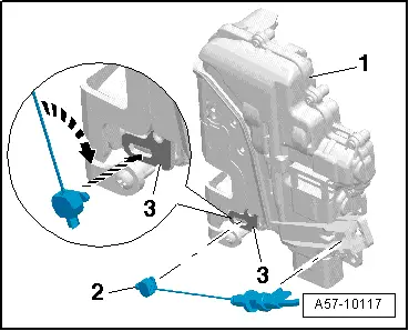
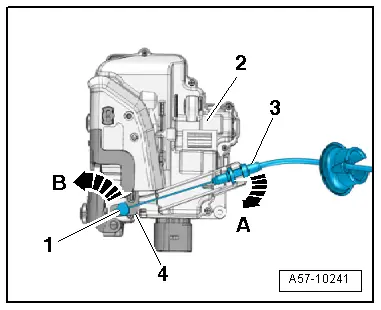
- Disengage the operating cable -3- at the door lock -2--arrow A-.
- Turn the nipple -1- 90º in the direction of the -arrow B- and remove it from the door opener operating lever -4-.
Installing
- Insert the nipple -2- in the door opener release lever -3--lower arrow-.
- Rotate the nipple 90º -upper arrow- and press the operating cable into the cable bracket on the door lock -1- until it engages audibly.
Further installation is the reverse order of removal.