Audi Q7: Timing Chain Cover, Removing and Installing
Left Timing Chain Cover, Removing and Installing
Special tools and workshop equipment required
- Hand Drill with Plastic Brush Attachment
- Protective Eyewear
- Sealant. Refer to the Parts Catalog.
 Caution
This procedure contains mandatory replaceable parts. Refer to component overview prior to starting procedure.
Mandatory Replacement Parts
- Bolts - Left timing chain cover
Removing
 Note
Note
During installation, all cable ties must be installed at the same location.
- Remove the left secondary air injection combination valve from the cylinder head (refer to → Chapter "Left Combination Valve, Removing and Installing") move to the side.
- Remove the left coolant pipe. Refer to → Chapter "Left Coolant Pipe, Removing and Installing".
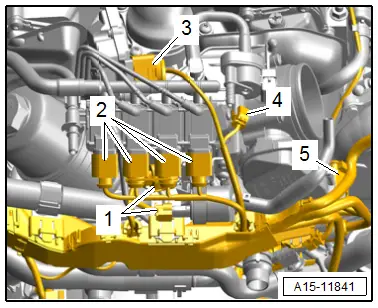
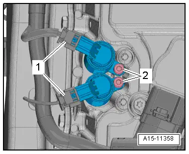
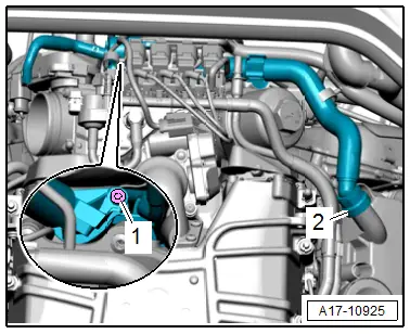
- Disconnect the connectors -1- for the Camshaft Adjustment Valve 2 -N208- and Exhaust Camshaft Adjustment Valve 2 -N319-.
 Note
Note
Ignore -2-.

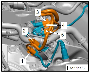
- Disconnect the connectors -1 to 4- and free up the wires.
 Note
Note
Ignore -5-.
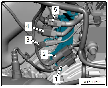
- Remove the connectors -3, 4, and 5- from the bracket and move to the side.
 Note
Note
Ignore -1 and 2-.
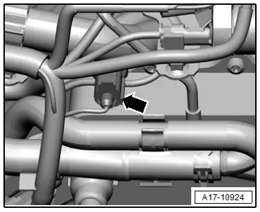
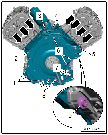
- Disconnect the connector -arrow- from the Oil Pressure Switch -F22- and free up the wire.
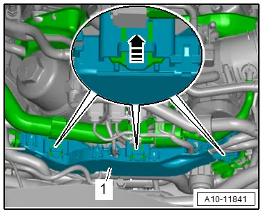
- Release the retainers in direction of -arrow- and remove wiring duct -1- toward the rear.
- Press the wiring duct to the side and secure them with a cable tie.
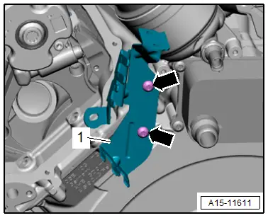
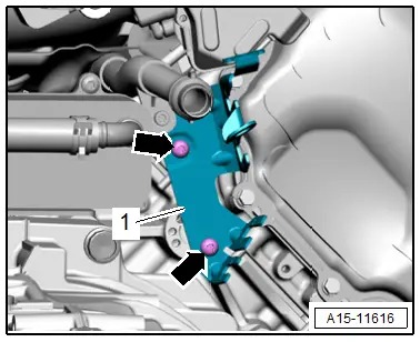
- Remove the bolts -arrows- and the bracket -1- for the connectors.
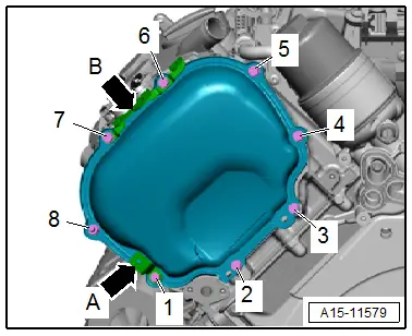
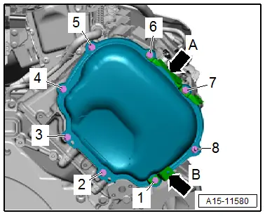
- Remove the bolts -1 through 8- and remove the brackets -A and B arrows-.
- Carefully loosen the left timing chain cover for example with a scraper from the adhesive and remove.
Installing
 Note
Note
- Replace the bolts that were tightened with an additional turn after removing them.
- Replace the O-rings after removing them.
- Remove any old sealant from the sealing surfaces.
 Caution
Risk of contaminating the lubricating system.
Cover open engine components.
 WARNING
Risk of eye injury.
Wear protective eyewear!
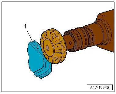
- Remove the sealant residue on the timing chain cover -1- and cylinder head, for example using a rotating plastic brush.
- Clean any oil or grease off the sealing surfaces.

 Note
Note
Note the expiration date for the sealant.
- Cut the tube nozzle at the front marking (tube nozzle diameter: approximately 2 mm).
 Caution
There is a risk that the lubrication system could be blocked by excess sealant.
Do not apply sealant bead thicker than indicated.
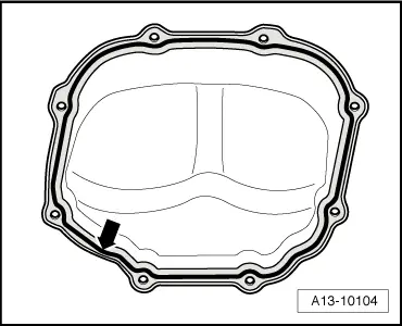
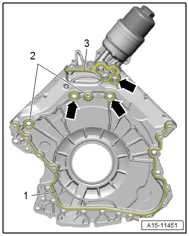
- Apply the sealant bead -arrow- to the clean sealing surfaces on the timing chain cover as shown.
- Sealant bead thickness: 2.5 mm
 Note
Note
The timing chain cover must be installed within five minutes after applying the sealant
- Attach the left timing chain cover and brackets -A and B arrows- and then tighten the bolts. Refer to → Fig. "Left Timing Chain Cover - Tightening Specification and Sequence".
Installation is performed in reverse order of removal, while noting the following:
 Note
Note
Replace the O-ring after removing.
- Install the left coolant pipe. Refer to → Chapter "Left Coolant Pipe, Removing and Installing".
- Install the secondary air injection combination valve. Refer to → Chapter "Left Combination Valve, Removing and Installing".
- Connections and wire routing. Refer to → Wiring diagrams, Troubleshooting & Component locations.

Tightening Specifications
- Refer to → Fig. "Left Timing Chain Cover - Tightening Specification and Sequence"
- Tower brace. Refer to → Suspension, Wheels, Steering; Rep. Gr.40; Suspension Strut and Upper Control Arm; Overview - Suspension Strut and Upper Control Arm.
Right Timing Chain Cover, Removing and Installing
Special tools and workshop equipment required
- Hand Drill with Plastic Brush Attachment
- Protective Eyewear
- Sealant. Refer to the Parts Catalog.
 Caution
This procedure contains mandatory replaceable parts. Refer to component overview prior to starting procedure.
Mandatory Replacement Parts
- Bolts - Right Timing Chain Cover
Removing
 Note
Note
During installation, all cable ties must be installed at the same location.
- Remove the Secondary Air Injection Pump Motor -V101-. Refer to → Chapter "Secondary Air Injection Pump Motor -V101-, Removing and Installing".
- Remove the Heated Oxygen Sensor -G39-. Refer to → Chapter "Heated Oxygen Sensor -G39-, Removing and Installing".
- Disconnect the secondary air hoses -arrows- by pressing the release buttons on both sides.
- Remove the nuts -1 and 3- and the bolt -2- and move the secondary air injection pipe to the side.
- Remove the right secondary air injection combination valve from the cylinder head (refer to → Chapter "Right Combination Valve, Removing and Installing") move to the side.
- Disconnect the connectors -1- for the Camshaft Adjustment Valve 1 -N205- and Exhaust Camshaft Adjustment Valve 1 -N318-.
 Note
Note
Ignore -2-.
- Remove the connectors -1 to 4- from the bracket and move to the side.
 Note
Note
Ignore -5-.
- Free up the wiring harness at the right timing chain cover.
- Remove the bolts -1 through 8- and remove the brackets -A and B arrows-.
- Carefully loosen the right timing chain cover for example with a scraper from the adhesive and remove.

Installing
 Note
Note
- Replace the bolts that were tightened with an additional turn after removing them.
- Replace the O-rings after removing them.
- Remove any old sealant from the sealing surfaces.
 Caution
Risk of contaminating the lubricating system.
Cover open engine components.
 WARNING
Risk of eye injury.
Wear protective eyewear!
- Remove the sealant residue on the timing chain cover -1- and cylinder head, for example using a rotating plastic brush.
- Clean any oil or grease off the sealing surfaces.
 Note
Note
Note the expiration date for the sealant.
- Cut the tube nozzle at the front marking (tube nozzle diameter: approximately 2 mm).
 Caution
There is a risk that the lubrication system could be blocked by excess sealant.
Do not apply sealant bead thicker than indicated.
- Apply the sealant bead -arrow- to the clean sealing surfaces on the timing chain cover as shown.
- Sealant bead thickness: 2.5 mm
 Note
Note
The timing chain cover must be installed within five minutes after applying the sealant

- Attach the right timing chain cover and brackets -A and B arrows- and then tighten the bolts. Refer to → Fig. "Right Timing Chain Cover - Tightening Specification and Sequence".
Installation is performed in reverse order of removal, while noting the following:
 Note
Note
Replace the O-ring after removing.
- Install the secondary air injection combination valve. Refer → Chapter "Right Combination Valve, Removing and Installing".
- Install the Heated Oxygen Sensor -G39-. Refer to → Chapter "Heated Oxygen Sensor -G39-, Removing and Installing".
- Connections and wire routing. Refer to → Wiring diagrams, Troubleshooting & Component locations.
Tightening Specifications
- Refer to → Fig. "Right Timing Chain Cover - Tightening Specification and Sequence"
- Refer to → Chapter "Overview - Valvetrain"
- Refer to → Chapter "Overview - Secondary Air Injection System"
- Tower brace. Refer to → Suspension, Wheels, Steering; Rep. Gr.40; Suspension Strut and Upper Control Arm; Overview - Suspension Strut and Upper Control Arm.
Lower Timing Chain Cover, Removing and Installing
Special tools and workshop equipment required
- Elbow Assembly Tool -T10118-
- Hand Drill with Plastic Brush Attachment
- Protective Eyewear
- Sealant. Refer to the Parts Catalog.
 Caution
This procedure contains mandatory replaceable parts. Refer to component overview prior to starting procedure.
Mandatory Replacement Parts
- Bolts - Lower timing chain cover
- Gasket - Right Cylinder Head
- O-rings - Lower timing chain cover
- Seal - Lower timing chain cover
Removing
- The transmission is removed. Refer to → 8-Speed Automatic Transmission 0D5; Rep. Gr.37; Transmission, Removing and Installing; Transmission, Removing.
- Engine oil drained.
 Note
Note
During installation, all cable ties must be installed at the same location.
- Remove the drive plate. Refer to → Chapter "Drive Plate, Removing and Installing".
- Remove the left and right timing chain covers. Refer to → Chapter "Left Timing Chain Cover, Removing and Installing" and → Chapter "Right Timing Chain Cover, Removing and Installing".
- Remove the oil filter element.
- Remove the engine oil cooler. Refer to → Chapter "Engine Oil Cooler, Removing and Installing".
- Remove the generator. Refer to → Electrical Equipment; Rep. Gr.27; Generator; Generator, Removing and Installing.
- Remove the bolts -arrows- and the bracket -1-.
- Remove the bolt -1-.
- Remove the connection with the crankcase ventilation hose, free up and pivot to the side.
 Note
Note
Ignore -2-.
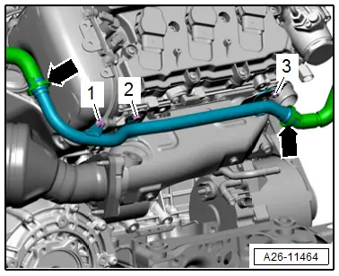
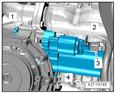
- Disconnect the connector -3- from the starter by sliding the retainer back and pressing the release down.
- Remove the nut -2- for the wire and then remove the starter.
 Note
Note
- For clarity, the installation position is shown with the engine support removed.
- Ignore -1 and 4-.
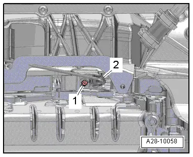
- Disconnect the connector -2- for the Engine Speed Sensor -G28-.
 Note
Note
Ignore -1-.
- Remove the bolts -arrows-.
- Loosen and remove the bolts -1 through 9- in a diagonal sequence.
- Carefully loosen and remove the lower timing chain cover from the bond.
- Press the transmission side of the crankshaft seal out of the lower timing chain cover.
Installing
Install in reverse order of removal and note the following:
 Note
Note
- Replace the bolts that were tightened with an additional turn after removing them.
- Replacing the seals after removal.
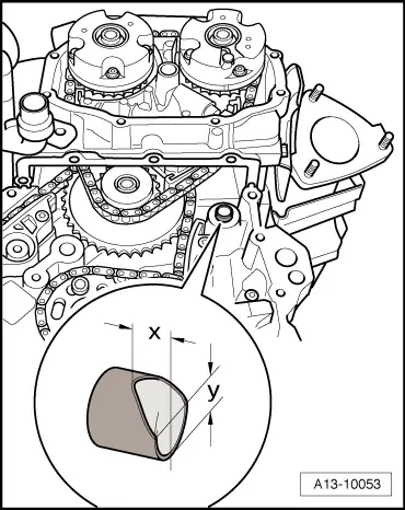
- Remove the right upper alignment sleeve from the cylinder block.
- Grind the alignment sleeve down at an angle as shown
- Dimension -x- = 6.5 mm.
- Dimension -y- = 8 mm.
- Insert the alignment sleeve in the cylinder block so that the angled side faces up.
 Note
Note
Because of the chamfer, the lower timing chain cover can be positioned more easily when the cylinder head is installed.
 Caution
Risk of contaminating the lubricating system.
Cover open engine components.
 WARNING
Risk of eye injury.
Wear protective eyewear!
- Remove any sealant residue still on the lower timing chain cover -1-, cylinder block and cylinder head with a rotating plastic brush.
- Clean any oil or grease off the sealing surfaces.
- Always clean the threaded holes for the engine/transmission threaded connection in the cylinder block using a thread tap before installing the transmission.

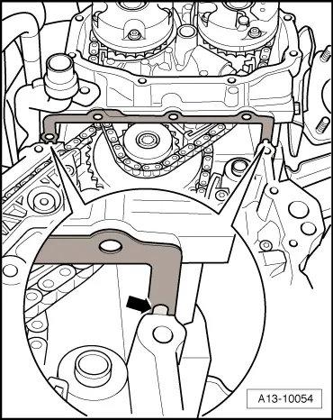
- Clean old sealant out of the holes -arrow- in the cylinder head seals.
 Note
Note
With the cylinder head installed, the holes in the cylinder head gasket are only half visible.
 Caution
Risk of damaging the cylinder head gasket.
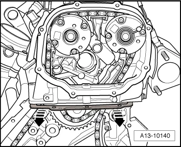
Only bend the ends of cylinder head gaskets slightly, do not kink.
 Note
Note
Replace the cylinder head gasket if kinked.
- Only bend the ends of the cylinder head gaskets downward slightly in direction of -arrows- until the upper sealing surface of the gasket and cylinder head can also be cleaned.
- Clean any oil and grease off the upper and lower cylinder head seals.

 Note
Note
Note the expiration date for the sealant.
- Cut the tube nozzle at the front marking (tube nozzle diameter: approximately 2 mm).
- Thinly coat the top and bottom of the sealing surfaces for the cylinder head gaskets with sealant by bending the gaskets downward again slightly in direction of -arrows-.
- Use a flat object such as a feeler gauge to coat the surface between the cylinder head and gasket.
- Fill the cleaned cylinder head gasket holes -arrow- with sealant.

 Caution
There is a risk that the lubrication system could be blocked by excess sealant.
Do not apply sealant bead thicker than indicated.
- Apply sealant beads -1 through 3- on the clean lower timing chain cover sealing surfaces as shown in the illustration.
- The groove on the sealing surface must be completely filled with sealant.
- The sealant beads must be 1.5 to 2.0 mm above the sealing surface.
- Draw through the sealant bead -3- as shown, even though the groove is intermittent.
 Note
Note
The timing chain cover must be installed within five minutes after applying the sealant
- Insert the seals -arrows- in the grooves on the lower timing chain cover.
- Position the lower timing chain cover, guiding it diagonally from below to the sealing surface on the cylinder block and cylinder head.
- When positioning, make sure that the cylinder head gaskets are not damaged.
- Tighten the bolts. Refer to → Fig. "Lower Timing Chain Cover - Tightening Specification and Sequence".
Installation is performed in reverse order of removal, while noting the following:
- Install the crankshaft seal on the transmission side. Refer to → Chapter "Crankshaft Seal, Replacing, Transmission Side".
- Install the engine oil cooler. Refer to → Chapter "Engine Oil Cooler, Removing and Installing".
- Install the generator. Refer to → Electrical Equipment; Rep. Gr.27; Generator; Generator, Removing and Installing.
- Install the oil filter element.
- Install the left and right timing chain covers. Refer to → Chapter "Timing Chain Cover, Removing and Installing".
- Install the drive plate. Refer to → Chapter "Drive Plate, Removing and Installing".
- Fill with engine oil and check the oil level.

Tightening Specifications
- Refer to → Fig. "Lower Timing Chain Cover - Tightening Specification and Sequence"
- Refer to → Chapter "Overview - Crankcase Ventilation"
- Refer to → Electrical Equipment; Rep. Gr.27; Starter; Overview - Starter.

