Audi Q7: Door Lock Cable, Removing and Installing
 NOTICE
Risk of damaging the operating cable by deforming it.
- Never sharply bend or kink the operating cable.
Removing
- Remove the door lock. Refer to → Chapter "Door Lock, Removing and Installing".
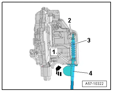
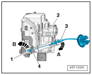
Cable, Disengaging at Door Lock:
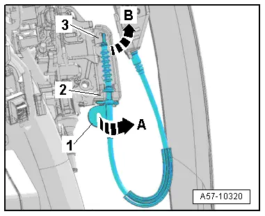
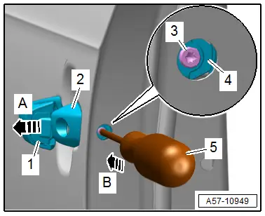
- Turn the operating cable at the lever -2- 90º in the -direction of arrow A- and remove it from the cable bracket -1-.
- Rotate the operating cable on the door lock release lever -3- in the direction of -arrow B-.
- The operating cable must be aligned with the opening on the release lever.
- Disengage the operating cable from the release lever.
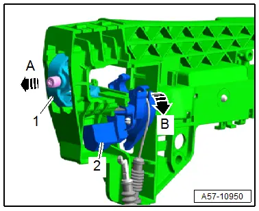
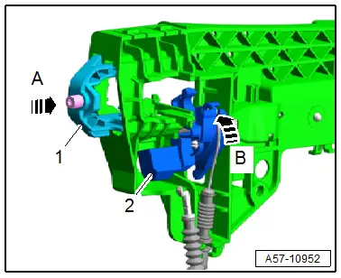
Operating Lever, Loosening from Locking Mechanism on Removed Mounting Bracket:
- Slightly remove the retaining bracket -1--arrow A- at the same time hold the operating lever -2-.
- Let the operating lever turn back slowly -arrow B-.
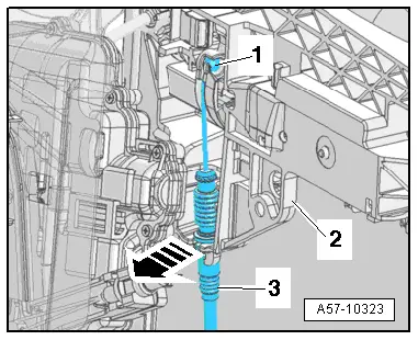
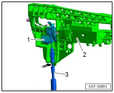
Cable, Disengaging on Installed Mounting Bracket:
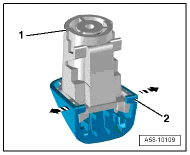
- Disengage the operating cable -1- on the operating lever by pressing the cable -3- out of the support bracket on the mounting bracket -2--arrow-.
- Remove the operating cable.
Installing
Cable, Engaging at Door Lock:
- Engage the operating cable -3- in the door lock operating lever -2-.
- Insert the operating cable in the cable bracket -1- and rotate the lever -4- 90º -arrow-.
- The lever must engage audibly with the locking tab on the cable bracket.
Cable, Engaging at Mounting Bracket:
- Engage the operating cable -3- on the operating lever -1-.
- Engage the operating cable in the cable bracket on the mounting bracket -2--arrow-.
Operating Lever, Locking on Removed Mounting Bracket
- Turn the operating lever -2- all the way in the direction of the -arrow B- and lock with the retaining bracket -1--arrow A-.
Further installation is the reverse order of removal.
Housing, Removing and Installing
Removing
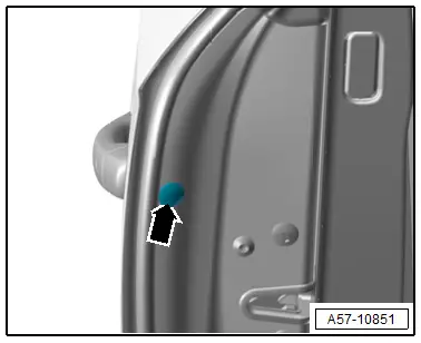
- Remove the cap -arrow-.
- Pull the door handle -1- all the way -arrow A- and hold it.
- Remove the clamping screw -3- all the way using a screwdriver -5-
- Push the retaining bracket -4- for the housing inward until it engages -arrow B-.
- The door handle is now locked in the "open" position.
- Remove the housing -2- from the mounting bracket.
Installing
Install in reverse order of removal.
Tightening Specifications
- Refer to → Chapter "Overview - Door Handle and Mounting Bracket"
Housing Cap, Removing and Installing
Removing
- Remove the housing. Refer to → Chapter "Housing, Removing and Installing".
- Spread the clips -arrows- and remove the cover cap -2- from the housing -1- using an awl if necessary.
Installing
Install in reverse order of removal.
Trim Molding Cap, Removing and Installing
Removing
- Remove the housing. Refer to → Chapter "Housing, Removing and Installing".
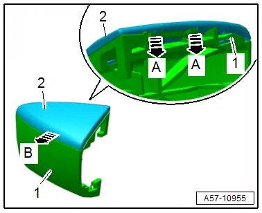
- Release the retainers -A arrows-.
- Remove the trim molding -2- from the cap -1--arrow B-.
Installing
Install in reverse order of removal.
Door Lock, Removing and Installing
Removing
 NOTICE
Risk of damaging the operating cable by deforming it.
- Never sharply bend or kink the operating cable.
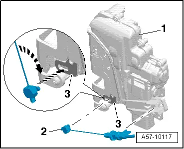
- Remove the door window guide rail. Refer to → Chapter "Door Window Guide Rail, Removing and Installing".
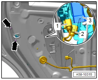
- Remove the cover -3-.
- Disconnect the connectors -1 and 2- and free up the wires.
- Remove the bolts -arrows- and carefully guide out the door lock from the door to the opening for the door inner cover.
- Disengage the operating cable from the operating lever on the door lock. Refer to → Chapter "Door Lock Cable, Removing and Installing".
Installing
Install in reverse order of removal.
Tightening Specifications
- Refer to → Chapter "Overview - Door Handle and Door Lock"
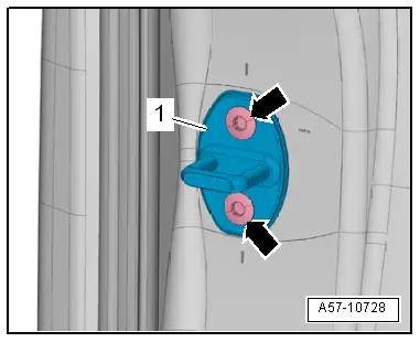
Striker, Removing and Installing
Removing
- Remove the bolts -arrows- and remove the striker -1-.
Installing
Install in reverse order of removal and note the following:
- Adjust the striker. Refer to → Chapter "Striker, Adjusting".
Tightening Specifications
- Refer to → Chapter "Overview - Door Handle and Door Lock"
Door Opener Operating Cable, Removing and Installing
 NOTICE
Risk of damaging the operating cable by deforming it.
- Never sharply bend or kink the operating cable.
Removing
- Remove the door lock and move it to the side. Refer to → Chapter "Door Lock, Removing and Installing".
- Disengage the operating cable -3- at the door lock -2--arrow A-.
- Turn the nipple -1- 90º in the direction of the -arrow B- and remove it from the door opener operating lever -4-.
Installing
Install in reverse order of removal and note the following:
- Insert the nipple -2- in the door opener operating lever -3--lower arrow-.
- Rotate the nipple 90º -upper arrow- and press the operating cable into the cable bracket on the door lock -1- until it engages audibly.