Audi Q7: Driver and Front Passenger Seat Adjustment Control Head -E470-/-E471-, Removing and Installing
Special tools and workshop equipment required
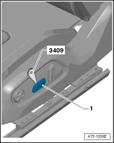
- Trim Removal Wedge -3409-
Removing
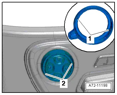
- Carefully pry the seat adjustment actuator -1- using the -3409- from the retainers.
- Repeat the procedure on the backrest adjustment actuator.
- Remove the seat side trim on side sill side. Refer to → Chapter "Seat Side Trim On Side Sill Side, Removing and Installing".
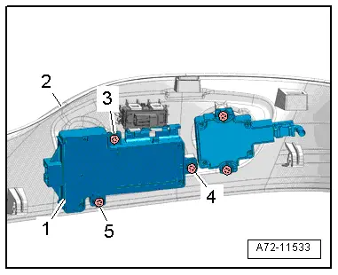
- Remove the bolts -3 to 5-.
- Remove the control head -1- from the side sill seat side trim -2-.
Installing
Install in reverse order of removal.
Installation notes, for example tightening specifications, replacing components. Refer to → Chapter "Overview - Seat Pan, Power Seat Adjustment Actuator/Switch".
Driver and Front Passenger Seat Lumbar Support Adjustment Switch -E176-/-E177-, Removing and Installing
Special tools and workshop equipment required
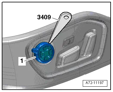
- Trim Removal Wedge -3409-
Removing
- Remove the seat side trim on the side sill side. Refer to → Chapter "Seat Side Trim On Side Sill Side, Removing and Installing".
- Carefully unclip the rocker -1- from the switch module using the -3409-.
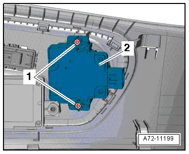
- Remove bolts -1- and switch module -2-.
Installing
Install in reverse order of removal and note the following:
- Insert trim with the tabs -1- in the grooves -2- on the switch module and press on it until it engages audibly.
Installation notes, for example tightening specifications, replacing components. Refer to → Chapter "Overview - Seat Pan, Power Seat Adjustment Actuator/Switch".
Driver Side Massage Function Button -E670-/ Front Passenger Massage Function Button -E671-, Removing and Installing
Removing
- Remove the seat side trim on side sill side. Refer to → Chapter "Seat Side Trim On Side Sill Side, Removing and Installing".
- Press out massage function button -1- from the trim and remove it by releasing the locks -arrows-.
Installing
Install in reverse order of removal.
Installation notes, for example tightening specifications, replacing components. Refer to → Chapter "Overview - Seat Pan, Power Seat Adjustment Actuator/Switch".
Lumbar Support Adjustment Motors -V125-/-V126-/-V129-/-V130-, Removing and Installing
Special tools and workshop equipment required
- Pop Rivet Pliers -VAG1753B-
- Hand drill
- Protective Eyewear
Removing
 WARNING
- Follow all safety precautions when working on pyrotechnic components. Refer to → Chapter "Safety Precautions for Pyrotechnic Components".
- Before handling pyrotechnic components (for example, disconnecting the connector), the person handling it must "discharge static electricity". This can be done by briefly touching the door striker pin, for example.
- Remove the front seat. Refer to → Chapter "Front Seat, Removing and Installing".
- Fasten the front seat on the -VAS6136-. Refer to → Chapter "Front Seat, Mounting on Fixture for Seat Repair".
- Remove the backrest seat cover and cushion. Refer to → Chapter "Backrest Cover and Cushion, Removing and Installing, Seat without Pneumatic Components".
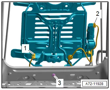
- Detach the connectors -1 and 2- at the lumbar support forward/back and height adjustment motors.
- Cut through the cable tie and free up the wiring harness on the lumbar support.
 WARNING
Risk of eye injury.
Wear protective eyewear!
- Drill out the rivet -3-.
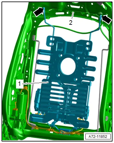
- Move the lower lumbar support -1- forward, pivot it out of the backrest frame, disengage it from the backrest frame -2--arrows- and remove it.
Installing
- Engage the lumbar support -1- at the top in the backrest frame -2--arrows-, pivot the bottom toward the rear and insert in the backrest frame.
- Rivet the lumbar support to the backrest frame.
 WARNING
- Follow all safety precautions when working on pyrotechnic components. Refer to → Chapter "Safety Precautions for Pyrotechnic Components".
- Before handling pyrotechnic components (for example, connecting the connector), the person handling it must "discharge static electricity". This can be done by briefly touching the door striker pin, for example.
- Observe all measures when installing the front seat. Refer to → Chapter "Front Seat, Removing and Installing".
Further installation is the reverse order of removal.
Installation notes, for example tightening specifications, replacing components. Refer to → Chapter "Overview - Front Backrest, Lumbar Support".
Seat Functions Control Module, Removing and Installing
Removing
- Switch off the ignition.
- Unscrew the front seat and tip to the rear with the wires attached. Refer to → Chapter "Front Seat, Removing and Installing".
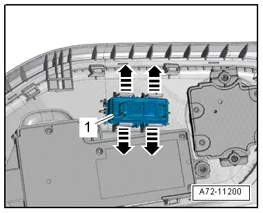
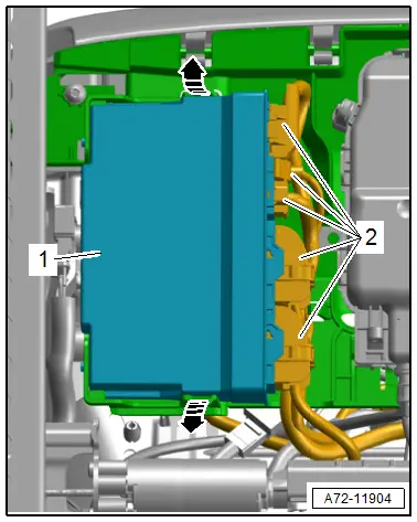
- Release retaining tabs in direction of -arrows-.
- Remove the control module -1- from the bracket
- Release the connector safety catch and disconnect the connectors -2-.
Installing
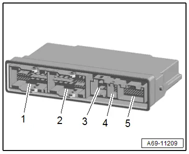
- If the control module was replaced, follow the sequence when connecting the connectors.
- First connect the connector -5- (coding connector), then connect the other connectors -1 to 4-.
Further installation is the reverse order of removal.
Installation notes, for example tightening specifications, replacing components. Refer to → Chapter "Overview - Front Seat".
Seat Cushion Fan, Removing and Installing
Special tools and workshop equipment required
- Pop Rivet Nut Pliers -VAS5073A-
- Engine/Transmission Holder - Seat Repair Fixture -VAS6136-
- Mini-grinder, commercially available
- Protective Eyewear
Removing
 WARNING
- Follow all safety precautions when working on pyrotechnic components. Refer to → Chapter "Safety Precautions for Pyrotechnic Components".
- Before handling pyrotechnic components (for example, disconnecting the connector), the person handling it must "discharge static electricity". For example, this can be done by briefly touching the door striker.
- Remove the front seat. Refer to → Chapter "Front Seat, Removing and Installing".
- Fasten the front seat on the -VAS6136-. Refer to → Chapter "Front Seat, Mounting on Fixture for Seat Repair".
 WARNING
Risk of eye injury.
Wear protective eyewear!
- Carefully separate the pop rivets -arrows- using a mini grinder.
- Remove the cover -1- for the fan.
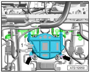
- Disconnect the connector -2-.
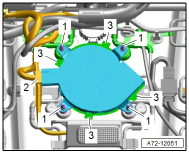
- Spray the rubber fasteners -1- for the elastic fan bracket with silicone-free lubricating spray and remove the fan from the rubber fasteners.
- Disengage the tabs -3- on the seat cushion fan and remove the fan.
Installing
Install in reverse order of removal.
Installation instructions: for example tightening specifications, replacing components. Refer to → Chapter "Overview - Front Seat".

