Audi Q7: Engine, Securing to Engine and Transmission Holder
Special tools and workshop equipment required
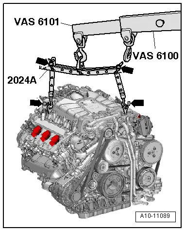
- Engine Sling -2024A-
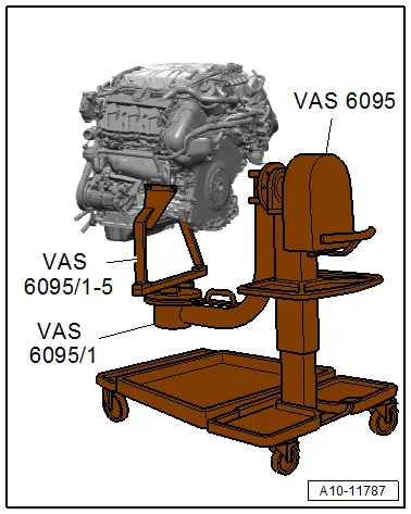
- Engine and Gearbox Bracket -VAS6095A-
- Engine/Transmission Holder - Universal Mounting -VAS6095/1- and Engine/Transmission Holder - V6 FSI Bracket -VAS6095/1-5-
- Shop Crane -VAS6100-
- Lift Arm Extension -VAS6101-
Procedure
- Engine/transmission assembly removed and separated on Scissor Lift Table -VAS6131B-. Refer to → Chapter "Engine and Transmission, Separating".
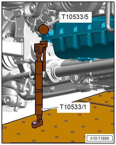
- Engine secured with the Engine Support -T10533-.
![]() WARNING
WARNING
Risk of accident!
The engine may only be transported in the manner described and without the transmission.
- Engage the Engine Sling -2024A- on the engine lifting eyes and on the Shop Crane -VAS6100- with Lift Arm Extension - VAS6101- as shown in the illustration.
![]() Note
Note
To be aligned to the center of gravity of the assembly, the rails with holes of the lifting hooks must be inserted as shown.
![]() WARNING
WARNING
There is the risk of an accident.
Lifting hooks and pins on the engine sling must be secured with securing pins in direction of -arrows-.
- Tension the engine slightly with the shop crane, but do not lift.
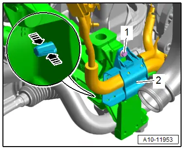
- Remove the bolt -1-.
- Release the catches in direction of -arrows- and free up the bracket -2- for the wires from the subframe.
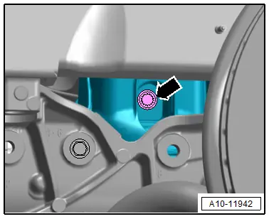
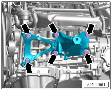
- Remove engine bracket left and right bolt -arrow-.
- Remove the Engine Support -T10533/1- with -T10533/5- from the engine.
- Raise the engine from the engine support.
- Remove the bolts -arrows- and the left engine support with the A/C compressor bracket.
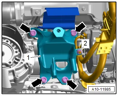
- Remove the nut -2- and free up the ground wire at the engine support -1-.
- Remove the bolts -arrows- and the right engine support.
- Secure the starter on the engine.
- Fasten the engine with the Engine/Transmission Holder - Universal Mounting -VAS6095/1- and Engine/Transmission Holder - V6 FSI Bracket -VAS6095/1-5- on the Engine and Gearbox Bracket -VAS6095A- to 40 Nm as shown.