Audi Q7: EVAP System
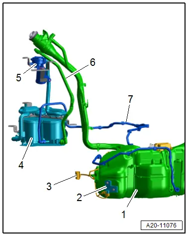
Connection Diagram - EVAP System
Connection Diagram - EVAP System, Market-Specific North America
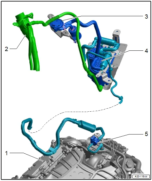
1 - Engine
2 - Fuel Tank
3 - Fuel Tank Pressure Sensor -G400-
4 - EVAP Canister
5 - EVAP Canister Purge Regulator Valve 1 -N80-
Overview - EVAP System
Overview - EVAP System, Market-Specific North America
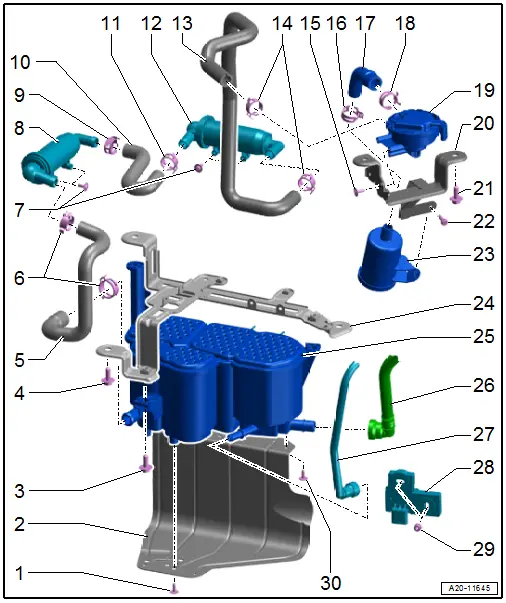
1 - Bolt
- 2.4 Nm
- Quantity: 3
2 - Protective Plate
3 - Bolt
- 20 Nm
- Quantity: 2
4 - Bolt
- 20 Nm
- Quantity: 3
5 - Hose
6 - Hose Clamps
- Must be appropriate for the model type. Refer to the Parts Catalog.
7 - Bolt
- 2.4 Nm
- Quantity: 4
8 - Filter
- Refer to → Chapter "EVAP Canister, Removing and Installing".
9 - Hose Clamp
- Must be appropriate for the model type. Refer to the Parts Catalog.
10 - Hose
11 - Hose Clamp
- Must be appropriate for the model type. Refer to the Parts Catalog.
12 - Filter
- Refer to → Chapter "EVAP Canister, Removing and Installing".
13 - Hose
14 - Hose Clamps
- Must be appropriate for the model type. Refer to the Parts Catalog.
15 - Bolt
- 2.2 Nm
- Quantity: 3
16 - Hose Clamp
- Must be appropriate for the model type. Refer to the Parts Catalog.
17 - Hose
18 - Hose Clamp
- Must be appropriate for the model type. Refer to the Parts Catalog.
19 - Fuel Tank Pressure Sensor -G400-
- Component location: at the right rear in the wheel housing under the wheel housing liner
- Refer to → Chapter "Fuel Tank Pressure Sensor -G400-, Removing and Installing".
20 - Bracket
21 - Bolt
- 20 Nm
- Quantity: 2
22 - Bolt
- 5 Nm
23 - Air Filter
- Refer to → Chapter "Fuel Tank Pressure Sensor -G400-, Removing and Installing".
24 - Bracket
25 - EVAP Canister
- Component location: at the right rear in the wheel housing under the wheel housing liner
- Refer to → Chapter "EVAP Canister, Removing and Installing".
26 - Bleeder Line
- From the fuel tank
- Connector couplings, separating and connecting. Refer to → Chapter "Connector Couplings, Disconnecting".
27 - Bleeder Line
- To the EVAP Canister Purge Regulator Valve 1 -N80-
- Connector couplings, separating and connecting. Refer to → Chapter "Connector Couplings, Disconnecting".
- Clipped to the underbody
28 - Fuel Tank Leak Detection Control Module -J909-
- Component location: Right front on the fuel tank
- Refer to → Chapter "Fuel Tank Leak Detection Control Module -J909-, Removing and Installing".
29 - Nut
- 1.6 Nm
- Quantity: 2
30 - Bolt
- 8 Nm
- Quantity: 2
EVAP Canister, Removing and Installing
EVAP Canister, Removing and Installing
Removing
- Observe the safety precautions. Refer to → Chapter "Safety Precautions".
- Follow the guidelines for clean working conditions. Refer to → Chapter "Guidelines for Clean Working Conditions".
- Remove the right rear wheel housing liner. Refer to → Body Exterior; Rep. Gr.66; Wheel Housing Liner; Rear Wheel Housing Liner, Removing and Installing.
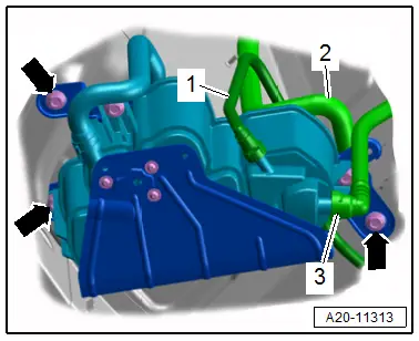
- Disconnect the vent and bleeder lines -1, 2 and 3-. Disconnect the connector couplings. Refer to → Chapter "Connector Couplings, Disconnecting".
- Remove the bolts -arrows- and remove the EVAP canister.
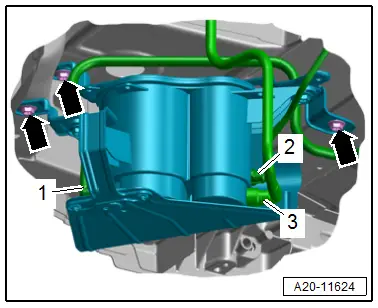
- Remove the vent hose -2- by loosening the hose clamp.
- Disconnect the bleeder lines -1 and 3-. Disconnect the connector couplings. Refer to → Chapter "Connector Couplings, Disconnecting".
- Remove the bolts -arrows- and remove the EVAP canister.
Filter, Removing
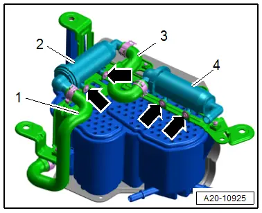
- Loosen the hose clamp to remove the hose -1-.
- Remove the bolts -arrows-.
- Remove the filters -2 and 4- and remove the hose -3- by loosening the hose clamp.
Installing
Install in reverse order of removal.
Tightening Specifications
- Refer to → Chapter "Overview - EVAP System"
- Refer to → Body Exterior; Rep. Gr.66; Wheel Housing Liner; Overview - Rear Wheel Housing Liner.
Fuel Tank Pressure Sensor -G400-, Removing and Installing
Removing
- Observe the safety precautions. Refer to → Chapter "Safety Precautions".
- Follow the guidelines for clean working conditions. Refer to → Chapter "Guidelines for Clean Working Conditions".
- Remove the right rear wheel housing liner. Refer to → Body Exterior; Rep. Gr.66; Wheel Housing Liner; Rear Wheel Housing Liner, Removing and Installing.
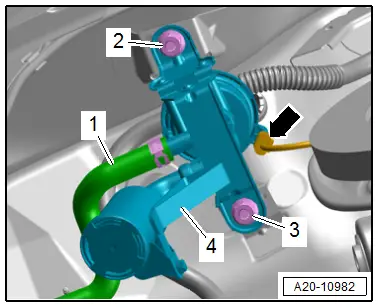
- Disconnect the connector -arrow-.
- Remove the vent hose -1- by loosening the hose clamp.
- Remove the bolts -2 and 3-.
- Remove the bracket -4- with the Fuel Tank Pressure Sensor -G400- and air filter.
- Remove the vent hose -2- by loosening the hose clamp.
- Remove the bolts -3-.
- Remove the Fuel Tank Pressure Sensor -G400--4- from the bracket.
Air Filter, Removing
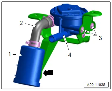
- Remove the vent hose -2- by loosening the hose clamp.
- Remove the bolt -arrow-.
- Remove leak detection system air filter -1-.
Installing
Install in reverse order of removal.
Tightening Specifications
- Refer to → Chapter "Overview - EVAP System, Market-Specific North America"
- Refer to → Body Exterior; Rep. Gr.66; Wheel Housing Liner; Overview - Rear Wheel Housing Liner.
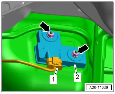
Fuel Tank Leak Detection Control Module -J909-, Removing and Installing
Removing
- Observe the safety precautions. Refer to → Chapter "Safety Precautions".
- Remove the right rear underbody trim panel. Refer to → Body Exterior; Rep. Gr.66; Underbody Trim Panel; Underbody Trim Panels, Removing and Installing.
- Release the connector safety catch and disconnect the connector -1-.
- Remove the nuts -arrows- and remove the control module -2-.
Installing
Install in reverse order of removal.
Tightening Specifications
- Refer to → Chapter "Overview - EVAP System, Market-Specific North America"
- Refer to → Body Exterior; Rep. Gr.66; Underbody Trim Panel; Overview - Underbody Trim Panels.
Fuel System, Checking for Leaks
- The function of the leak detection system is based on the premise that the fuel system creates a natural vacuum when the fuel in the fuel tank becomes colder.
- The Fuel Tank Pressure Sensor -G400--5- senses the vacuum in the bleeder line -6- near the EVAP canister -4-. The Fuel Tank Leak Detection Control Module -J909--2- is attached directly to the wall of the fuel tank -1- and monitors the temperature inside the fuel tank. The system is considered to be closed if the measured vacuum is 2.5 mbar (0.036 psi). If there is no vacuum, then there is a leak in the fuel system, which will result in an entry in the engine control module DTC memory.
3 - Signal wire to Engine Control Module -J623-
7 - Bleeder line to engine