Audi Q7: Accelerator Mechanism
Overview - Accelerator Pedal Module
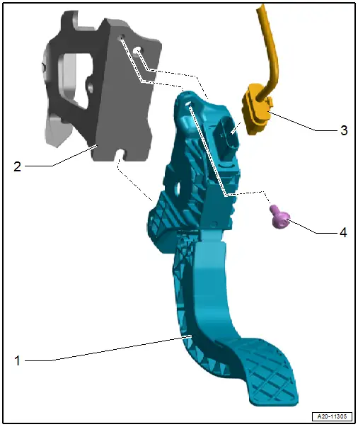
1 - Accelerator Pedal Module
- With Accelerator Pedal Position Sensor -G79- and Accelerator Pedal Position Sensor 2 -G185-
2.5 mbar (0.036 psi)
- Check using the Vehicle Diagnostic Tester.
- Refer to → Chapter "Accelerator Pedal Position Sensors -G79-/-G185-, Removing and Installing".
- Depending on the engine/transmission combination, an adaptation may need to be performed after replacing.
- If a corresponding menu item is in the engine electronics tree structure under "functions", perform the adaptation using the Vehicle Diagnostic Tester.
2 - Pedal Bracket
3 - Connector
- Make sure it is attached securely
4 - Bolt
- 8 Nm
Accelerator Pedal Position Sensors -G79-/-G185-, Removing and Installing
Removing
- Remove the driver side instrument panel cover. Refer to → Body Interior; Rep. Gr.68; Storage Compartments and Covers; Driver Side Instrument Panel Cover, Removing and Installing.
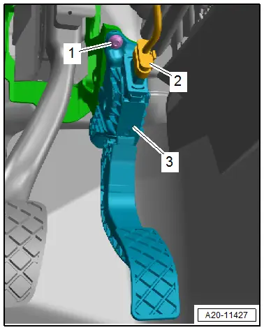
- Press the release and disconnect the connector -2-.
- Remove the bolt -1-.
- Disengage the lower accelerator pedal module -3- from the pedal bracket and remove.
Installing
Install in reverse order of removal and note the following:
- Engage the accelerator pedal module on the bottom of the pedal bracket, insert the centering pin and tighten the bolt.
 Note
Note
- Depending on the engine/transmission combination, an adaptation may need to be performed after replacing.
- If a corresponding menu item is in the engine electronics tree structure under "functions", perform the adaptation using the Vehicle Diagnostic Tester.
Tightening Specifications
- Refer to → Chapter "Overview - Accelerator Pedal Module"
- Refer to → Body Interior; Rep. Gr.68; Storage Compartments and Covers; Overview - Driver Side Instrument Panel Cover.

