Audi Q7: Fuel Pump
Transfer Fuel Pump -G6-, Checking
Special tools and workshop equipment required
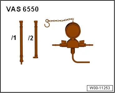
- Pressure Tester Kit -VAS6550- with Pressure Tester Kit - Hose 2 -VAS6550/2-
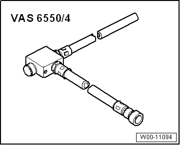
- Pressure Regulator Valve -VAS6550/4-
- Vehicle Diagnostic Tester
- Fuel-Resistant Measuring Container
A - Checking Fuel Delivery Rate
- Follow all test requirements. Refer to → Chapter "Test Conditions".
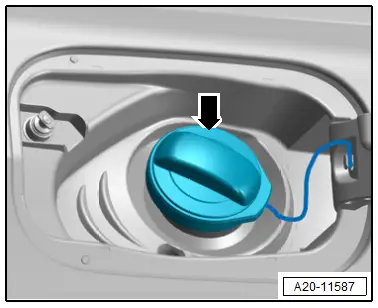
- Open the fuel filler door.
- Remove the fuel filler cap -arrow-.
 WARNING
There is a risk of injury because the fuel is under high pressure.
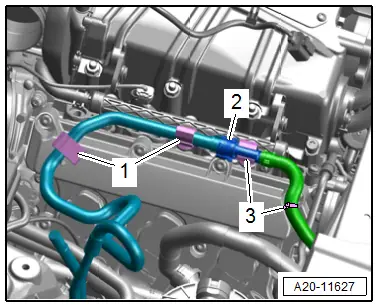
To reduce the pressure in the fuel system, lay clean cloths around the connection point and carefully loosen the connection point.
- Free up the fuel hose from the brackets -1 and 3- and disconnect the connector coupling -2-. Refer to → Chapter "Connector Couplings, Disconnecting".
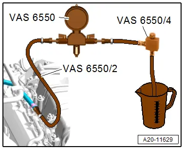
- Connect the Pressure Tester Kit -VAS6550- to the fuel supply line with the Pressure Tester Kit - Hose 2 -VAS6550/2-.
- Connect the Pressure Regulator Valve -VAS6550/4- and hold the hose in a fuel-resistant measuring container.
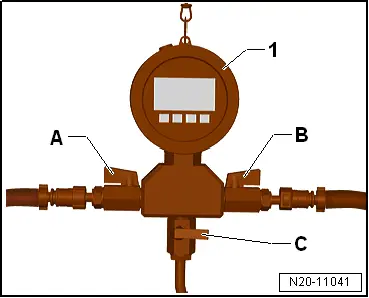
- Switch on the Pressure Tester Kit -VAS6550--1- by pressing the On/Off button.
 Note
Note
To measure the fuel delivery rate, an initial pressure must be created in the fuel line which the fuel pump must work against during measurement. Adjust the initial pressure using the Pressure Regulator Valve -VAS6550/4- as follows:
- Open the shut-off valves -A and B-.
- The lever points in the flow direction.

 Caution
Risk of fuel leak.
- The shut-off valve -C- must be closed.
- The lever is perpendicular to the flow direction.
- Connect the Vehicle Diagnostic Tester.
- Switch the ignition on.
- Select and start OBD mode.
- Drivetrain
- Engine
- 01 - OBD-capable systems
- 01 - Engine electronics
- Basic setting
- Empty fuel tank
- Start the basic setting without measured values: the fuel pump starts.
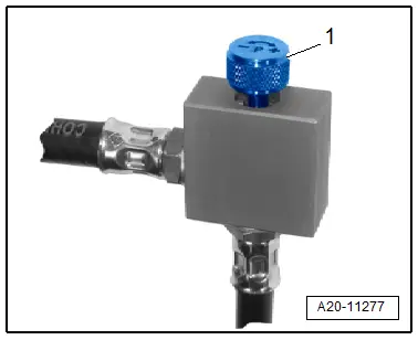
- Turn the adjusting screw -1- on the Pressure Regulator Valve -VAS6550/4- to create an initial pressure in the fuel system until the correct initial pressure value is reached.
- Specified value: 4.5 bar (65.27 psi) pressure.
- Do not turn the adjusting screw -1- any farther.
- Press the Stop button.
- Empty the measuring container.
- To measure, press the Start button again and let the fuel pump run for 15 seconds.
- After 15 seconds, press the Stop button.
- Check the fuel delivery rate in the measuring container.
- Specified value: minimum delivery rate 800 cm3/15 s.
If the Minimum Delivery Rate Is Attained:
- The fuel delivery unit with the fuel filter, fuel pressure regulator and fuel supply line is OK.
If the Minimum Delivery Rate Is Not Obtained, the following Malfunctions May Be Present:
- Fuel delivery unit with integrated fuel filter is faulty.
- Fuel pressure regulator in the fuel delivery unit is faulty.
- Fuel supply line is crushed.
 Note
Note
To locate the fault in more detail, perform the "pressure test in the fuel supply line", described as follows.
B - Pressure Test in the Fuel Supply Line
- Connect the measuring setup as if measuring the fuel delivery rate.
- Vehicle Diagnostic Tester still connected.
- Switch on the Pressure Tester Kit -VAS6550--1- by pressing the On/Off button.
- Open the shut-off valves -A and B-.
- The lever points in the flow direction.
 Caution
Risk of fuel leak.
- The shut-off valve -C- must be closed.
- The lever is perpendicular to the flow direction.
- Press Start on the Vehicle Diagnostic Tester display: The fuel pump starts running.
- If the fuel flows without bubbles, close the drain -B-, so that the fuel pressure increases.
- The lever is perpendicular to the flow direction.
- Read the fuel pressure in the Pressure Tester Kit -VAS6550-:
- Specified value: 6.0 to 8.0 bar (87.02 to 116.03 psi).
- Press the Stop button.
If the Specified Value Is Obtained, Although the Fuel Delivery Rate Is Not OK.
- Fuel filter in the fuel delivery unit is plugged of the fuel supply line is crushed.
If the Specified Value Is Not Attained
- Fuel delivery unit or fuel pressure regulator in the fuel tank is faulty.
C - Checking Residual Pressure
- Watch the pressure fall on the Pressure Tester Kit -VAS6550- while checking the residual pressure and checking for leaks:
- There still must be a pressure of at least 3 bar (43.51 psi) after 10 minutes.
If the Residual Pressure Drops Below 3 bar (43.51 psi)
- Check the fuel lines and their connections for leaks.
- The fuel pump check valve in the fuel pump leaks: replace the fuel delivery unit. Refer to → Chapter "Fuel Delivery Unit/Fuel Level Sensor, Removing and Installing".
Assembling
Assemble in the reverse order of removal. Note the following:
- The ignition must be off.
 Note
Note
Decrease the fuel pressure by opening the shut-off valves -B and C- and letting the fuel run into the measuring container before removing the pressure gauge -1-.
- Remove the Pressure Tester Kit -VAS6550- with the connecting lines.
- Attach the fuel supply line so that it clicks into place.
- Press the fuel supply line on again and pull to make sure the connector coupling is engaged correctly.

Suction Jet Pump, Removing and Installing
Fuel tank is divided into a left and a right chamber. To move the volume of fuel from the left fuel tank chamber to the right baffle housing -1- of the fuel delivery unit -2-, a suction jet pump -3- is utilized.
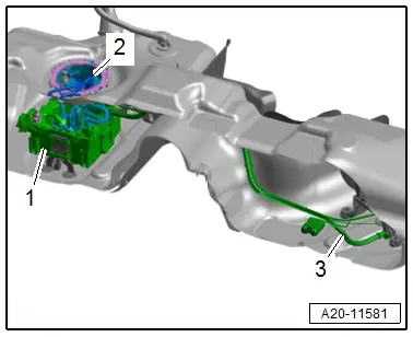
Suction Jet Pump Function
Function of the suction jet pump is based on a simple physical principle: a suction jet from the electrical fuel pump is compressed by a nozzle in the suction jet pump and is thereby accelerated. This acceleration causes the surrounding fuel to be drawn in and be forced to the baffle housing of the fuel delivery unit.
Malfunctions from Faulty Suction Jet Pump
 Caution
Tow-in due to faulty suction jet pump.
If the suction jet pump is defective, the vehicle can stop running due to lack of fuel even if the fuel tank is up to 1/4 filled.
If the suction jet pump does not function, up to 15 liters (3.96 gallons) of fuel (up to approximately 1/4 of the tank) remains in left chamber of fuel tank which cannot be extracted by the fuel delivery unit.
If vehicle stops running, although the fuel tank is approximately 1/4 filled, proceed as follows:
- Connect the Vehicle Diagnostic Tester.
- Switch the ignition on.
- Select and start OBD mode.
- Drivetrain
- Engine
- 01 - OBD-capable systems
- 01 - Engine electronics
- Basic setting
- Drain fuel tank
- Start the selected program and follow the instructions in the display of the Vehicle Diagnostic Tester.
If the fuel pump is OK, but no fuel is being delivered:
- Fill approximately five liters (1.32 gallons) of fuel.
- Start the engine.
If the engine now starts:
- The suction jet pump is not delivered separately; replace the fuel tank. Refer to → Chapter "Fuel Tank, Removing and Installing".
Fuel Pump Control Module -J538-, Removing and Installing
Special tools and workshop equipment required
- Safety Gloves
Removing
- Observe the safety precautions. Refer to → Chapter "Safety Precautions".
- Follow the guidelines for clean working conditions. Refer to → Chapter "Guidelines for Clean Working Conditions".
- Move the front seats all the way forward into the highest position.
- Switch off the ignition and place the ignition key outside of the vehicle.
- Remove the right rear and front sill panel. Refer to → Body Interior; Rep. Gr.70; Vehicle Interior Trim Panels; Sill Panel, Removing and Installing.
- Remove the bench seat / right and center single seats. Refer to → Body Interior; Rep. Gr.72; Rear Seats; Bench Seat/Single Seat, Removing and Installing.
- Remove the support for the right luggage compartment floor. Refer to → Body Interior; Rep. Gr.70; Luggage Compartment Trim Panels; Overview - Luggage Compartment Floor.
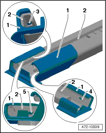
- Remove the cover -1- on the front passenger seat behind both seat rails, to do so release the tabs -3, 4 and 5- carefully on the seat rail -2-.
 Note
Note
The front passenger seat does not need to be removed.
- Remove the carpet under the seat rail.
- Remove the cover and connector station for the bench seat / single seat in the carpet.
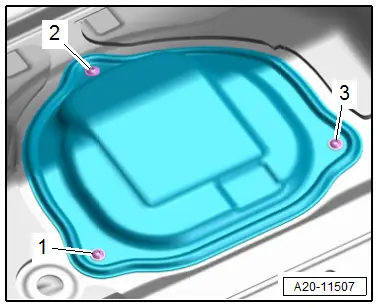
- Fold the carpet near the sealing flange cover to the side.
- Remove the bolts -1, 2 and 3- and remove the sealing flange cover.
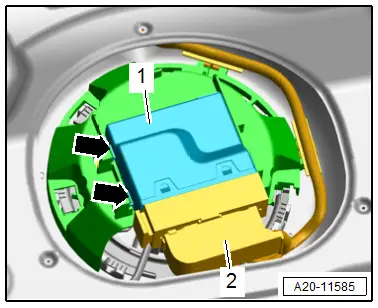
- Release the catches -arrows- using a screwdriver and remove the Fuel Pump Control Module -J538--1- from the bracket.
- Release the connector safety catch and disconnect the connector -2- for the Fuel Pump Control Module -J538-.
Installing
Install in reverse order of removal and note the following:
- Install the support for the luggage compartment floor. Refer to → Body Interior; Rep. Gr.70; Luggage Compartment Trim Panels; Overview - Luggage Compartment Floor.
- Install the bench seat / single seat. Refer to → Body Interior; Rep. Gr.72; Rear Seats; Bench Seat/Single Seat, Removing and Installing.
- Install the sill panel. Refer to → Body Interior; Rep. Gr.70; Vehicle Interior Trim Panels; Overview - Sill Panel Strip.
Tightening Specifications
- Refer to → Chapter "Overview - Fuel Delivery Unit/Fuel Level Sensor"
Special Tools
Special tools and workshop equipment required
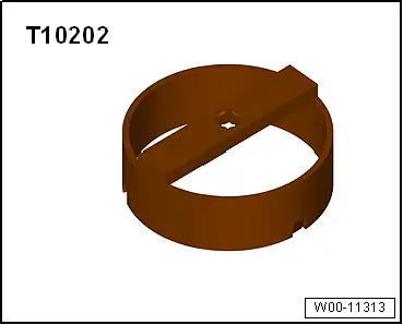
- Wrench - Fuel Sending Unit -T10202-
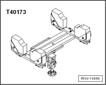
- Gearbox Support -T40173-
- Analog/Digital Multimeter -FLU83III-
- Connector Test Set -VAG1594D-
- Fuel Extraction Device -VAS5190A-
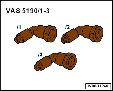
- Fuel Extraction - Adapter 2 -VAS5190/2-
- Pressure Tester Kit -VAS6550- with Pressure Tester Kit - Hose 2 -VAS6550/2-
- Pressure Regulator Valve -VAS6550/4-
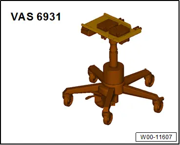
- Engine and Gearbox Jack -VAS6931-
- Vehicle Diagnostic Tester
- Safety Gloves
Revision History
DRUCK NUMBER: A005A011021