Audi Q7: Emissions Control System
Overview - Emissions Control System
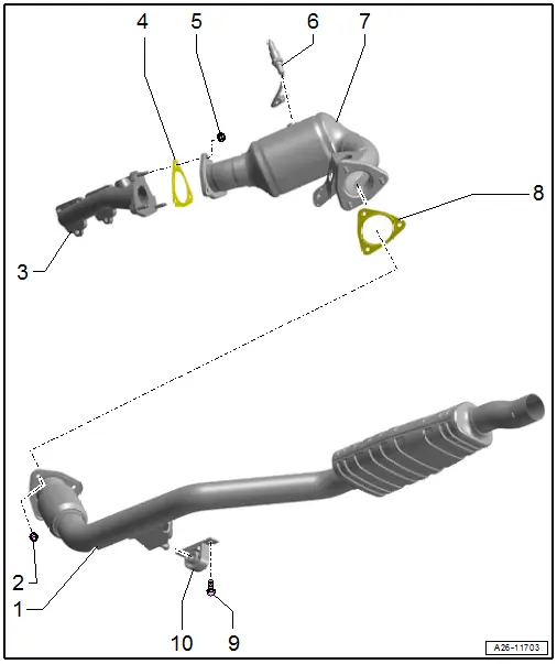
1 - Front Muffler
- With the coupling, the coupling must not be bent more than 10º - otherwise it may be damaged
- Removing and installing. Refer to → Chapter "Front Muffler, Removing and Installing".
- Exhaust System, Installing without Tension. Refer to → Chapter "Exhaust System, Installing without Tension".
2 - Nut
- 23 Nm
- Replace after removing
3 - Exhaust Manifold
- Removing and installing. Refer to → Chapter "Exhaust Manifold, Removing and Installing".
4 - Seal
- Replace after removing
5 - Nut
- 23 Nm
- Replace after removing
- Coat the thread with hot bolt paste. Refer to the Parts Catalog.
6 - Oxygen Sensor after Three Way Catalytic Converter
- Cylinder bank 1 (right) Oxygen Sensor after Catalytic Converter -G130-
- Cylinder bank 2 (left) Oxygen Sensor 2 after Catalytic Converter -G131-
- Overview. Refer to → Chapter "Overview - Heated Oxygen Sensor".
7 - Catalytic Converter
- Protect from shocks and impact stress
- Removing and installing. Refer to → Chapter "Catalytic Converter, Removing and Installing".
- Individual components of the suspension. Refer to → Fig. "Individual Catalytic Converter Mounting Components"
8 - Seal
- Replace after removing
9 - Bolt
- 23 Nm
10 - Mount
- Replace if damaged
- Check the pretension. Refer to → Chapter "Exhaust System, Installing without Tension".
Individual Catalytic Converter Mounting Components
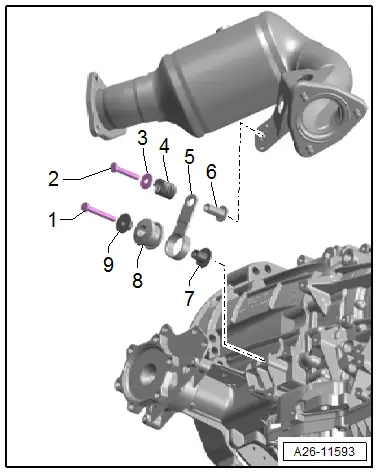
1 - Bolt - 23 Nm
2 - Bolt - 23 Nm
3 - Washer
4 - Pressure Spring
5 - Tab
6 - Spacer Sleeve
7 - Spacer Sleeve
8 - Buffer
9 - Spacer Sleeve
 Note
Note
The left mounting is shown.
Catalytic Converter, Removing and Installing
Left Catalytic Converter, Removing and Installing
 Caution
This procedure contains mandatory replaceable parts. Refer to component overview prior to starting procedure.
Mandatory Replacement Parts
- Lock Nuts - Front muffler
- Seals - Catalytic Converter
Special tools and workshop equipment required
- Engine and Gearbox Jack -VAS6931-
- Engine/Gearbox Jack - Gearbox Support -T10337-
Removing
 Note
Note
During installation, all cable ties must be installed at the same location.
- Remove the Oxygen Sensor 2 after Catalytic Converter -G131-. Refer to → Chapter "Heated Oxygen Sensor 2 -G108-/ Oxygen Sensor 2 after Catalytic Converter -G131-, Removing and Installing".
- Remove the left front muffler. Refer to → Chapter "Front Muffler, Removing and Installing".
- Remove the steering intermediate shaft. Refer to → Suspension, Wheels Steering; Rep. Gr.48; Steering Column; Steering Intermediate Shaft, Removing and Installing.
 Caution
Risk of damaging the decoupling element inside the front exhaust pipe.
Do not bend decoupling element in the front muffler more than 10º.
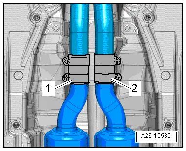
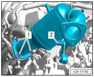
- Loosen the clamping sleeve -2-.
 Note
Note
Ignore -1-.
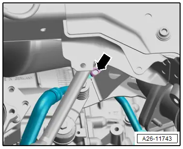
- Remove the bolt -arrow- for the ATF hose line.
- Remove the bolts -2 and 3- and remove the mounting.
- Remove the nuts -1-.
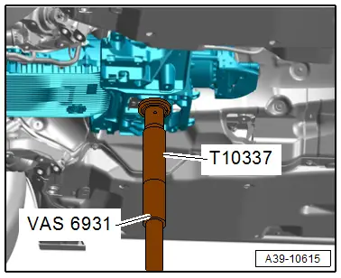
- Place the Engine/Gearbox Jack - Gearbox Support -T10337- on the Engine and Gearbox Jack -VAS6931- and position at the bottom of the transmission mount.
- Lift the transmission slightly with the engine and gearbox jack.
 WARNING
There is the risk of an accident.
The engine and gearbox jack may only be used during assembly and must not be left unsupervised under the vehicle.
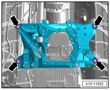
- Remove the tunnel crossmember bolts -arrows-.
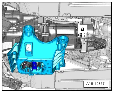
- Lower the tunnel crossmember to dimension -a- using the Engine and Gearbox Jack -VAS6931-.
- Dimension -a- = 55 mm maximum.
- Remove the left catalytic converter downward.
Installing
Install in reverse order of removal and note the following:
 Note
Note
Replace seals and self-locking nuts after disassembly.
- Install the steering intermediate shaft. Refer to → Suspension, Wheels Steering; Rep. Gr.48; Steering Column; Steering Intermediate Shaft, Removing and Installing.
- Install the Oxygen Sensor 2 after Catalytic Converter -G131-. Refer to → Chapter "Heated Oxygen Sensor 2 -G108-/ Oxygen Sensor 2 after Catalytic Converter -G131-, Removing and Installing".
Tightening Specifications
- Refer to → Chapter "Overview - Muffler"
- Refer to → Fig. "Individual Catalytic Converter Mounting Components"
- Refer to → 8-Speed Automatic Transmission; Rep. Gr.37; Subframe Mount; Overview - Subframe Mount.
- Refer to → 8-Speed Automatic Transmission; Rep. Gr.37; ATF Circuit; Overview - ATF Circuit.
Right Catalytic Converter, Removing and Installing
Special tools and workshop equipment required
- Engine and Gearbox Jack -VAS6931-
- Tensioning Strap -T10038-
- Engine/Gearbox Jack - Gearbox Support -T10337-
 Caution
This procedure contains mandatory replaceable parts. Refer to component overview prior to starting procedure.
Mandatory Replacement Parts
- Lock Nuts - Front muffler
- Seals - Catalytic Converter
Removing
 Note
Note
During installation, all cable ties must be installed at the same location.
- Remove the Oxygen Sensor after Three Way Catalytic Converter -G130-. Refer to → Chapter "Heated Oxygen Sensor -G39-, Removing and Installing".
- Remove the left and right front muffler. Refer to → Chapter "Front Muffler, Removing and Installing".
- Remove the subframe crossbrace. Refer to → Suspension, Wheels, Steering; Rep. Gr.40; Subframe; Subframe Crossbrace, Removing and Installing.
 Caution
There is a risk of damaging the suspension components.
If the subframe mount, steering gear or subframe crossbrace are not installed correctly, do not rest the vehicle on its wheels.
- Remove the right subframe shield. Refer to → Suspension, Wheels, Steering; Rep. Gr.40; Subframe; Subframe Shield, Removing and Installing.
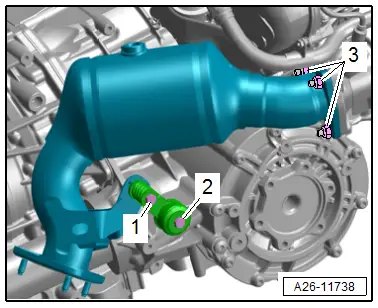
- Remove the bolts -1 and 2- and the mounting.
- Remove the nuts -3-.
- Place the Engine/Gearbox Jack - Gearbox Support -T10337- on the Engine and Gearbox Jack -VAS6931- and position at the bottom of the transmission mount.
- Lift the transmission slightly with the engine and gearbox jack.
 WARNING
There is the risk of an accident.
The engine and gearbox jack may only be used during assembly and must not be left unsupervised under the vehicle.

- Remove the tunnel crossmember bolts -arrows-.

- Lower the tunnel crossmember to dimension -a- using the Engine and Gearbox Jack -VAS6931-.
- Dimension -a- = 55 mm maximum.

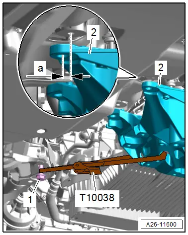
- Install the bolt -1- for the subframe crossbrace several turns in the subframe.
- Secure the Tensioning Strap -T10038- on the tunnel crossmember -2- and on the bolt, as shown.
- Pull the rear of the transmission to the left side to the dimension -a-.
- Dimension -a- = maximum 7 mm.
- Remove the right catalytic converter downward.
Installing
Install in reverse order of removal and note the following:
 Note
Note
Replace seals and self-locking nuts after disassembly.
- Install the Oxygen Sensor after Three Way Catalytic Converter -G130-. Refer to → Chapter "Heated Oxygen Sensor -G39-, Removing and Installing".
Tightening Specifications
- Refer to → Chapter "Overview - Muffler"
- Refer to → Fig. "Individual Catalytic Converter Mounting Components"
- Refer to → 8-Speed Automatic Transmission; Rep. Gr.37; Subframe Mount; Overview - Subframe Mount.
- Refer to → Suspension, Wheels, Steering; Rep. Gr.40; Subframe; Overview - Subframe.

