Audi Q7: Exhaust Manifold
Overview - Exhaust Manifold
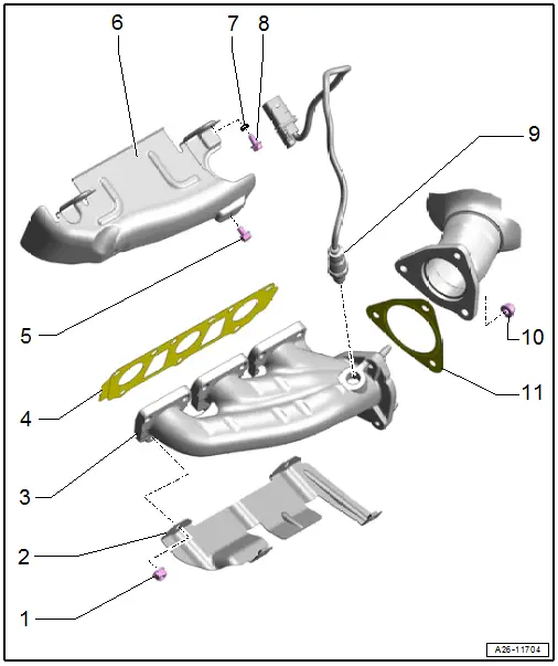
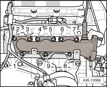
1 - Nut
- Replace after removing
- Coat the thread with hot bolt paste. Refer to the Parts Catalog.
- Tightening specification and sequence: left. Refer to → Fig. "Left Exhaust Manifold - Tightening Specification and Sequence", right → Fig. "Right Exhaust Manifold - Tightening Specification and Sequence"
2 - Bracket
- For the heat shield
3 - Exhaust Manifold
- Removing and installing. Refer to → Chapter "Exhaust Manifold, Removing and Installing".
4 - Seal
- Replace after removing
5 - Bolt
- 9 Nm
6 - Heat Shield
7 - Washer
8 - Bolt
- 9 Nm
9 - Heated Oxygen Sensor
- Before catalytic converter
- Removing and installing. Refer to → Chapter "Heated Oxygen Sensor -G39-, Removing and Installing".
10 - Nut
- 23 Nm
- Replace after removing
- Coat the thread with hot bolt paste. Refer to the Parts Catalog.
11 - Seal
- Replace after removing
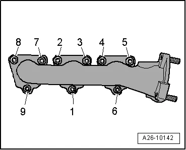
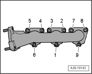
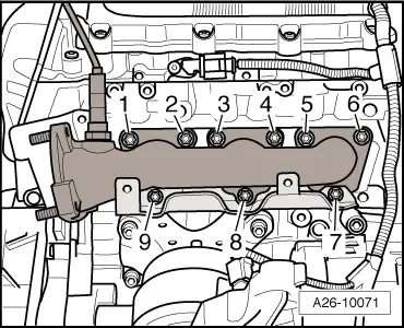
Left Exhaust Manifold - Tightening Specification and Sequence
 Note
Note
- Replace the nuts after removing.
- Coat the thread on the nut with hot bolt paste. Refer to the Parts Catalog.
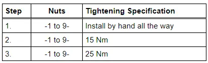
- Tighten the bolts in steps in the sequence shown:
Right Exhaust Manifold - Tightening Specification and Sequence
 Note
Note
- Replace the nuts after removing.
- Coat the thread on the nut with hot bolt paste. Refer to the Parts Catalog.
- Tighten the bolts in steps in the sequence shown:
Exhaust Manifold, Removing and Installing
Left Exhaust Manifold, Removing and Installing
 Caution
This procedure contains mandatory replaceable parts. Refer to component overview prior to starting procedure.
Mandatory Replacement Parts
- Lock Nuts - Front muffler
- Seals - Catalytic converter
- Nut - Exhaust manifold
- Seal - Exhaust manifold
Removing
 Note
Note
During installation, all cable ties must be installed at the same location.
- Remove the noise insulations. Refer to → Body Exterior; Rep. Gr.66; Noise Insulation; Noise Insulation, Removing and Installing.
- Remove the left coolant pipe. Refer to → Chapter "Left Coolant Pipe, Removing and Installing".
- Remove the left engine mount. Refer to → Chapter "Left Engine Mount, Removing and Installing".
- Remove the left front muffler. Refer to → Chapter "Front Muffler, Removing and Installing".
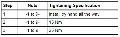
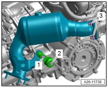
- Remove the bolt -3- and the nuts -1-.
- Remove the left catalytic converter from the exhaust manifold and move toward the rear.
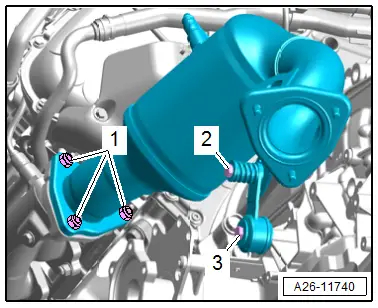
- Remove the bolts -arrows- and remove the heat shield -1-.
- Remove the nuts -1 and 8- and the heat shield bracket.
- Remove nuts -2 through 7 and 9- and remove the exhaust manifold.
Installing
Install in reverse order of removal and note the following:
 Note
Note
- Replace seal and self-locking nuts after disassembly.
- Coat the thread on the nut with hot bolt paste. Refer to the Parts Catalog.
- Position the exhaust manifold with the catalytic converter seal and tighten the nuts. Refer to → Fig. "Left Exhaust Manifold - Tightening Specification and Sequence".
- Install the left catalytic converter. Refer to → Chapter "Left Catalytic Converter, Removing and Installing".
- Install the left engine mount. Refer to → Chapter "Left Engine Mount, Removing and Installing".
- Install the left coolant pipe. Refer to → Chapter "Left Coolant Pipe, Removing and Installing".
Tightening Specifications
- Refer to → Fig. "Left Exhaust Manifold - Tightening Specification and Sequence"
- Refer to → Body Exterior; Rep. Gr.66; Noise Insulation; Overview - Noise Insulation.
Right Exhaust Manifold, Removing and Installing
 Caution
This procedure contains mandatory replaceable parts. Refer to component overview prior to starting procedure.
Mandatory Replacement Parts
- Lock Nuts - Front muffler
- Seals - Catalytic converter
- Nut - Exhaust manifold
- Seal - Exhaust manifold
Removing
 Note
Note
During installation, all cable ties must be installed at the same location.
- Remove the noise insulations. Refer to → Body Exterior; Rep. Gr.66; Noise Insulation; Noise Insulation, Removing and Installing.
- Remove the Secondary Air Injection Pump Motor -V101-. Refer to → Chapter "Secondary Air Injection Pump Motor -V101-, Removing and Installing".
- Remove the Heated Oxygen Sensor -G39-. Refer to → Chapter "Heated Oxygen Sensor -G39-, Removing and Installing".
- Remove the generator. Refer to → Electrical Equipment; Rep. Gr.27; Generator; Generator, Removing and Installing.
- Remove the Camshaft Position Sensor 3 -G300-. Refer to → Chapter "Camshaft Position Sensor, Removing and Installing".
- Remove the right front muffler. Refer to → Chapter "Front Muffler, Removing and Installing".
- Lower the subframe. Refer to → Suspension, Wheels, Steering; Rep. Gr.40; Subframe; Subframe, Lowering.
- Free up the Oxygen Sensor 2 after Catalytic Converter -G131- wire.
- Remove the bolts -1 and 2- and the mounting.
- Remove the nuts -3-.
- Remove the right catalytic converter from the exhaust manifold and move toward the rear.
 Note
Note
The installed position is shown in the illustration with the engine removed.
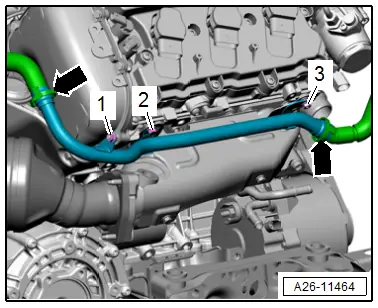
- Disconnect the secondary air hoses -arrows- by pressing the release buttons on both sides.
- Remove the nuts -1 and 3- and the bolt -2-.
- Remove the secondary air injection pipe, to do so lift the engine with the right spindle.
- Remove the bolts -arrows- and remove the heat shield -1-.
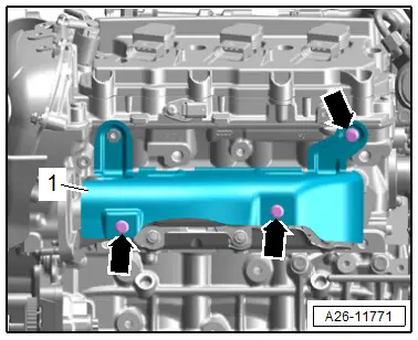
- Remove the nuts -7 and 9- and the heat shield bracket.
- Remove nuts -1 through 6 and 8- and the exhaust manifold.
Installing
Install in reverse order of removal and note the following:
 Note
Note
- Replace seals and self-locking nuts after disassembly.
- Coat the thread on the nut with hot bolt paste. Refer to the Parts Catalog.
- Secure all hose connections with hose clamps that match the ones used in series production. Refer to the Parts Catalog.
- Position the exhaust manifold with the catalytic converter seal and tighten the nuts. Refer to → Fig. "Right Exhaust Manifold - Tightening Specification and Sequence".
- Install the right catalytic converter. Refer to → Chapter "Right Catalytic Converter, Removing and Installing".
- Install the Heated Oxygen Sensor -G39-. Refer to → Chapter "Heated Oxygen Sensor -G39-, Removing and Installing".
- Install the subframe. Refer to → Suspension, Wheels, Steering; Rep. Gr.40; Subframe; Subframe, Lowering.
Tightening Specifications
- Refer to → Fig. "Right Exhaust Manifold - Tightening Specification and Sequence"
- Refer to → Chapter "Overview - Secondary Air Injection System"
- Refer to → Electrical Equipment; Rep. Gr.27; Generator; Overview - Generator.
- Refer to → Chapter "Overview - Ignition System"
- Refer to → Body Exterior; Rep. Gr.66; Noise Insulation; Overview - Noise Insulation.
Special Tools
Special tools and workshop equipment required
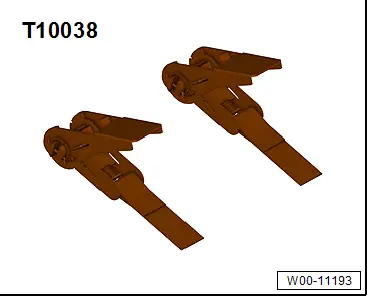
- Tensioning Strap -T10038-
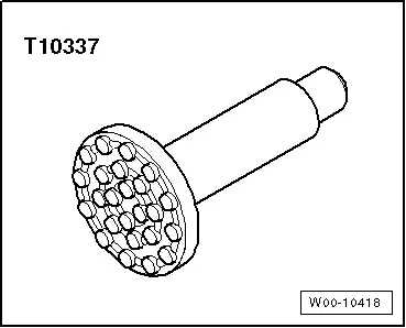
- Engine/Gearbox Jack - Gearbox Support -T10337-
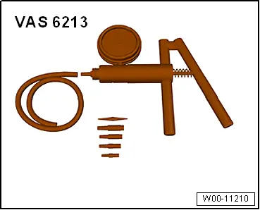
- Hand Vacuum Pump -VAS6213-
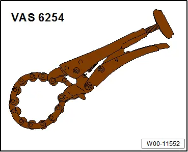
- Chain Pipe Cutter -VAS6254-
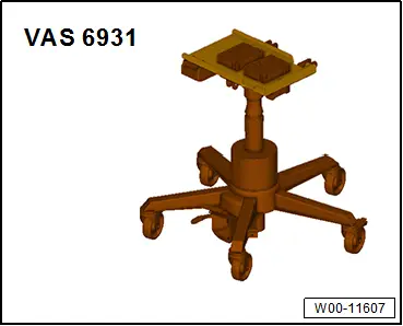
- Engine and Gearbox Jack -VAS6931-