Audi Q7: Final Drive, Removing and Installing
Rear Final Drive 0D2, Removing and installing. Audi Q7
Special tools and workshop equipment required
- -VAS6931-
 Caution
This procedure contains mandatory replaceable parts. Refer to component overview prior to starting procedure.
Mandatory Replacement Parts
- Bolt - Front Bonded Rubber Bushing to Rear Final Drive
Removing the Final Drive:
Pay attention to the general repair information. Refer to → Chapter "Repair Information".
- Tightening specifications. Refer to → Chapter "Overview - Rear Final Drive".
- Place the vehicle on a hoist.
- Remove the driveshaft on the rear final drive. Refer to → Chapter "Drive Shaft, Removing from Rear Final Drive and Installing".

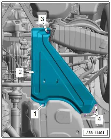
- Remove the bolts -1, 3 and 4- and the cover -2-.
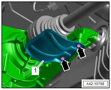
- Remove the bolts -arrows- and the left drive axle heat shield -1-.
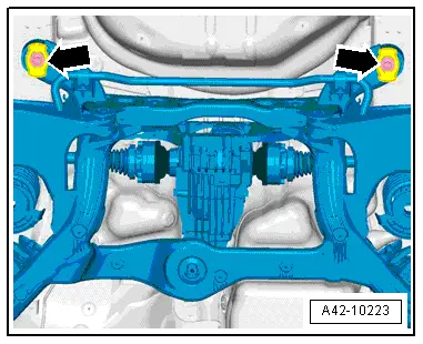
- Remove the bolts for the left and right drive axle -arrows-.
- Guide the drive axle out of the flange shaft and move it to the side.

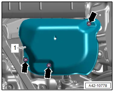
- Vehicles with air suspension: remove the nuts -arrows- and remove the cover for the air supply unit -1-.
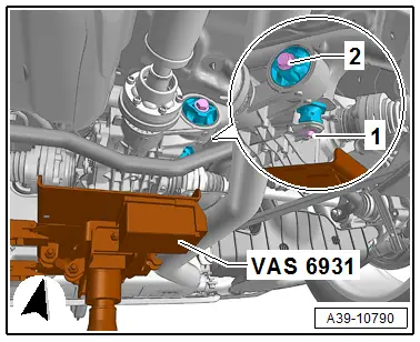
- Remove the nut -1-.
- Place the -VAS6931- with the Universal Transmission Support under the rear final drive.
- Remove the bolt -2-.

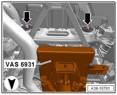
- Remove the bolts for the rear final drive -arrows-.
- Carefully lower the rear final drive.

Installing the Final Drive:
Install in reverse order of removal. Note the following:
- Tightening specifications. Refer to → Chapter "Overview - Rear Final Drive".
- Bring the rear final drive with the -VAS6931- and Universal Transmission Support into the installation position.
- Install the bolt -2- hand-tight.

- Install the bolts -arrows- for the rear final drive and tighten.

- Tighten the bolt -2- and nut -1-.
- Remove the -VAS6931- from under the final drive.

- Insert and tighten the drive axles. Refer to → Suspension, Wheels, Steering; Rep. Gr.42; Drive Axle; Drive Axle, Removing and Installing.
- Install the left flange shaft heat shield -1-.

- Install the driveshaft on the rear final drive. Refer to → Fig. "Install the Driveshaft on the Rear Final Drive.".
- Check the gear oil level in the rear final drive. Refer to → Chapter "Gear Oil, Checking Level".
- Install the underbody trim panel. Refer to → Body Exterior; Rep. Gr.66; Underbody Trim Panel; Underbody Trim Panels, Removing and Installing.
Rear Final Drive 0DB, 0D2 and 0D3, Removing and Installing, "Sport Differential", Audi A4
Special tools and workshop equipment required
- Engine and Gearbox Jack -VAS6931-
 Caution
This procedure contains mandatory replaceable parts. Refer to component overview prior to starting procedure.
Mandatory Replacement Parts
- Bolt - Front Bonded Rubber Bushing to Rear Final Drive
Final Drive, Removing:
Pay attention to the general repair information. Refer to → Chapter "Repair Information".
- Tightening specifications. Refer to → Chapter "Overview - Rear Final Drive".
- Place the vehicle on a hoist.
 NOTICE
Incorrect handling can damage the coupling.
- Do not bend the coupling more than 10º.
- Do not load the coupling.
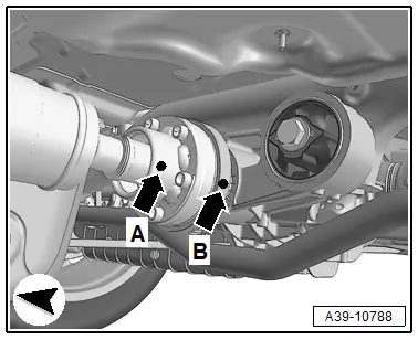
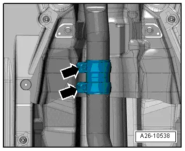
- Loosen the lock washer(s) -arrows- and separate the exhaust system.
- Tie up the front exhaust pipe(s) on the side to the underbody.
- Remove the rear section of the exhaust system. Refer to → Rep. Gr.26; Exhaust Pipes/Mufflers; Overview - Muffler.
- Remove the driveshaft on the rear final drive. Refer to → Chapter "Drive Shaft, Removing from Rear Final Drive and Installing".

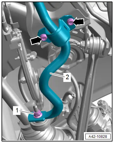
- Remove the bolts -arrows- for the right and left stabilizer bar clamp.
- Tilt the stabilizer bar slightly downward.
Final Drive 0D3 "Sport Differential"
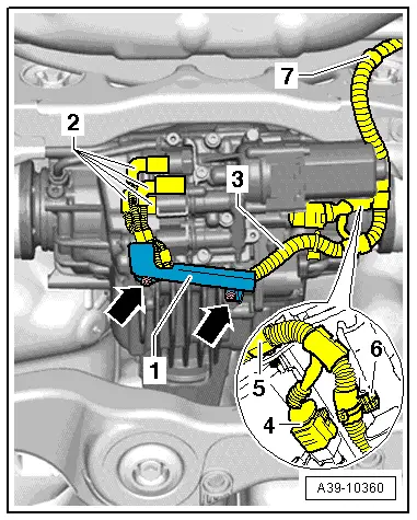
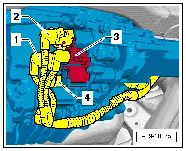
- Remove the bolts -arrows- and remove the bracket -1- from the rear final drive.
- Mark the connectors -2- for the Oil Pressure/Temperature Sensor and on the Clutch Valves.
- Disconnect the connectors -2- from the Oil Pressure/Temperature Sensor and the Clutch Valves.
- Disconnect the connector -4- from the AWD Pump -V415-.
- Unclip the wiring harness -3- from the final drive and the subframe and tie it up -5 through 7-.
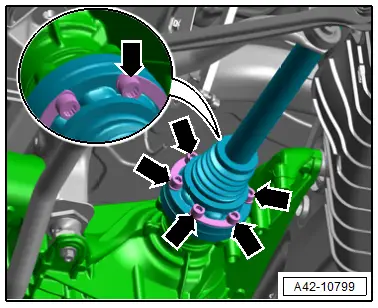
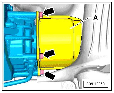
- Remove the heat shield -A- for the left and right drive axles from the rear final drive -arrows-.

Final Drive 0DB and 0D2
- Remove the bolts -arrows- and the left drive axle heat shield -1-.

- Remove the bolts for the left and right drive axle -arrows-.
Continuation for All
Lower the rear subframe as follows:
- Lower a maximum of 18 mm
- Remove both rear subframe bolts -arrows- straight until the distance on the right and left side to the longitudinal member is 18 mm.
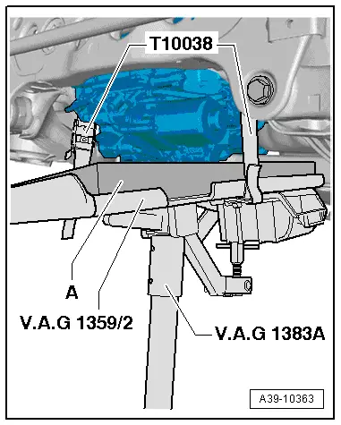
- Move the - VAS6931- with the Universal Transmission Support and a rubber or hard foam mat -A- under the rear final drive.
- The rubber or hard foam mat is needed to protect the Clutch Valves on the rear final drive from becoming damaged.
- Use a -T10038- to secure the rear final drive from falling.

- Remove the nuts -1-, if present.
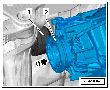
- Remove the bolt -2-.
- Remove the bolts for the rear final drive -arrows-.
- Press the rear final drive in the direction of -arrow- towards the right side of the vehicle.
- While doing so, guide the left drive axle -1- upward out of the flange shaft -2-.
- Then remove the right drive axle.
- Carefully lower the rear final drive.
- Go past the stabilizer bar when lowering.

Final Drive, Installing:
Install in reverse order of removal. Note the following:
- Tightening specifications. Refer to → Chapter "Overview - Rear Final Drive".
Final Drive 0D3 "Sport Differential"
- If the rear final drive was replaced, additional work is necessary. Refer to → Chapter "Final Drive 0D3 Sport Differential, Additional Work after Replacing".
Continuation for All
- Bring the rear final drive with the -VAS6931- and Universal Transmission Support into the installation position.
-A- = rubber or hard foam mat
- The rubber or hard foam mat is needed to protect the Clutch Valves on the rear final drive from becoming damaged.
- Insert the right drive axle into the final drive flange shaft.
- Press the final drive in the direction of -arrow- towards the right side of the vehicle.
- Guide the left drive axle -1- into the flange shaft -2-.
- Install the bolt -2- hand-tight.

- Install the new bolts for the rear final drive -arrows- and tighten.

- Tighten the bolt -2- and nut -1-.

- Tighten the subframe bolts -arrows-. Refer to → Suspension, Wheels, Steering; Rep. Gr.42; Subframe; Overview - Subframe.
- Remove the -VAS6931- from under the final drive.

- Tighten the stabilizer bar -arrows-. Refer to → Suspension, Wheels, Steering; Rep. Gr.42; Stabilizer Bar; Overview - Stabilizer Bar.

- Install the driveshaft on the rear final drive. Refer to → Fig. "Install the Driveshaft on the Rear Final Drive.".

- Tighten the drive axle. Refer to → Suspension, Wheels, Steering; Rep. Gr.42; Drive Axle; Drive Axle, Removing and Installing.
- Install the heat shield -1- for the left drive axle, if equipped.

Final Drive 0D3 "Sport Differential"
- Attach the drive axle heat shield -A- to the rear final drive -arrows- . Tightening specification: 20 Nm.
- Install the wiring harness -3- to the final drive and subframe -5 through 7-.
- Connect the connectors -4 and 2-. Pay attention to the marks made during the removal, that identify the allocation to the Oil Pressure/Temperature Sensor and which connectors go to the Clutch Valves.

 NOTICE
Wiring Harness, Clamping
Wiring harness damage
- Make sure the wiring harness -3- does not get pinched when installing the bracket -1- to the rear final drive.
- Attach the bracket -1- to the rear final drive and tighten the bolts -arrows-. Tightening specification: 9 Nm
Allocation of the connectors for the Oil Pressure/Temperature Sensor and Clutch Valves:
- -1- = Oil Pressure/Temperature Sensor 2 -G640- Connector
- -2- = Oil Pressure/Temperature Sensor -G437- Connector
- -3- = AWD Clutch Valve 2 -N446- Connector
- -4- = AWD Clutch Valve -N445- Connector
- Check the ATF inside the rear final drive. Refer to → Chapter "ATF Level, Checking, 0D3 Sport Differential".
Continuation for All
- Check the gear oil level in the rear final drive. Refer to → Chapter "Gear Oil, Checking Level".
- Install the rear exhaust system and align it without tension. Refer to → Rep. Gr.26; Exhaust Pipes/Mufflers; Overview - Muffler.
Final Drive 0D3 "Sport Differential"
- If the rear final drive 0D3 was replaced, additional work is necessary. Refer to → Chapter "Final Drive 0D3 Sport Differential, Additional Work after Replacing".
Final Drive 0D3 "Sport Differential", Additional Work after Replacing
- If the rear final drive was replaced, the following additional work is necessary.
- Bleed the hydraulic control module. Refer to Vehicle Diagnostic Tester.
- Program the rear final drive on the AWD Control Module -J492-. Refer to Vehicle Diagnostic Tester.
- The additional work can only be performed when the rear final drive is replaced.
Procedure:
- Connect the Vehicle Diagnostic Tester and turn on the ignition.
- Select the function 22 - Rear Final Drive Replacing in the vehicle diagnostic tester under Guided Functions in the directory 22- AWD Electronics.
- Follow all the instructions given by the Vehicle Diagnostic Tester exactly.
The new rear final drive is "adapted" on the AWD Control Module -J492- using the Vehicle Diagnostic Tester.
- A system check will take place when the function 22 - Rear Final Drive Replacing is complete. If malfunctions appear, then use "Guided Fault Finding" to correct them.

