Audi Q7: Fresh Air Door Motor -V438- Function, Removing and Installing
Fresh Air Door Motor -V438-, Removing and Installing
 Note
Note
- Therefore, perform the basic setting for the A/C system after installation of the adjustment motor. Refer to Vehicle Diagnostic Tester in the "Guided Fault Finding" function.
- Using the "output diagnostic test mode" and "basic setting" functions, the activation of A/C system electrical components can be tested if necessary (for example, allocation test). Refer to Vehicle Diagnostic Tester in the "Guided Fault Finding" function.
- Currently in this vehicle, all actuators are identical in construction. During the basic setting, the actuators are assigned and adapted corresponding to the switching sequence of the wiring. If this sequence does not conform with the specification, the actuators will adapt incorrectly and the door control will be wrong. Refer to → Chapter "Main Wiring Diagram for A/C System Actuators".
- After installing a new control motor, check the activation through the Front A/C Display Control Head -E87-, and the function of the actuator (correct position of the recirculation door and the back pressure/fresh air door). Refer to Vehicle Diagnostic Tester in the "Guided Fault Finding" function.
- Fresh Air Door Motor -V438- function. Refer to → Chapter "Fresh Air Door Motor -V438- Function".
Removing
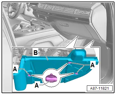
- Move the right front seat (front passenger seat) as far back as possible.
- Turn off the ignition.
- Remove screw clips -A-.
- Loosen the insulation -B- from the heater and A/C Unit air intake housing and remove.
 Caution
A/C system malfunctions in the case of interchanged control motors and/or connectors. Refer to → Chapter "Main Wiring Diagram for A/C System Actuators".
- The adjustment motors and connectors are identical. If they are installed or connected incorrectly, the corresponding doors cannot be properly adapted and/or activated.
- Clearly label the actuators and connectors prior to removal to prevent incorrect installation.
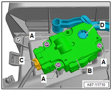
- Label the connector -C- (to prevent a mix up if several connectors are disconnected at the same time).
- Remove the bolts -A-.
- Remove the actuator -B- from the door shaft -D-.
- Disconnect the connector -C-.
Installing
Install in reverse order of removal. Note the following:
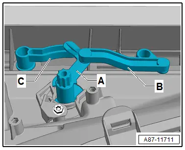
- Check the fasteners and lever to the doors -A, B and C- for proper assembly and ease of movement.
 Caution
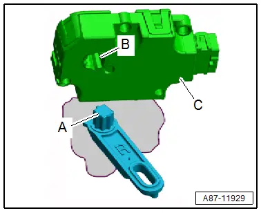
If the mount -B- for the actuator -C- is turned by hand, then the electronics in the actuator can be damaged.
 Note
Note
The actuator mount does not have a stop. It turns constantly if the actuator is activated. Therefore, this should not be activated with the adjustment motor removed.
- Check the shaft -A- and the mount -B- for the actuator -C-. They must be properly aligned so that they can be joined.
- Attach the actuator mount -B- to the door shaft -A-.
 Note
Note
Check the connection between the actuator mount and the shaft; there must not be any play.
- Connect the connector -C-.
- Tighten the bolts -A-.
- Route the wiring harness to the connector -C- so that it cannot come in contact with any moving parts.
- Perform the basic setting and the output diagnostic test mode of the A/C system. Refer to Vehicle Diagnostic Tester in the "Guided Fault Finding" function.

 Note
Note
- In this vehicle, the actuators are equipped with electronics. During the basic setting, a new control motor learns its position on the heater and A/C unit and can then be activated by the Front A/C Display Control Head -E87- (currently all actuators are identical). Refer to Vehicle Diagnostic Tester in the "Guided Fault Finding" function.
- During the basic setting, the actuators are assigned and adapted corresponding to the switching sequence of the wiring. If this sequence does not conform with the specification, the actuators will adapt incorrectly and the door control will be wrong. Refer to → Chapter "Main Wiring Diagram for A/C System Actuators".
- Check the DTC memory on the Front A/C Display Control Head -E87- and erase any displayed malfunctions. Refer to Vehicle Diagnostic Tester in the "Guided Fault Finding" function.
Fresh Air Door Motor -V438- Function
- The position of the fresh air- and back pressure door is visible via the air intake opening in the plenum chamber when the air recirculation is closed (if necessary, remove the plenum chamber cover and the cover over fresh air intake. Refer to → Chapter "Fresh Air Intake, Removing and Installing").
- For air flow regulation, the fresh air intake channel is closed partially via the back pressure door when at a high vehicle speeds (from approximately 80 km/h) by the Front A/C Display Control Head -E87- (the position of the recirculation door is specified by the Front A/C Display Control Head -E87-).
- To reduce the change in noise from the Fresh Air Blower -V2- due to the different air intake when switching from fresh air to recirculating air mode or vice versa, Fresh Air Door Motor -V438- and the Recirculation Door Motor -V133- are activated as follows:
- When switching from fresh air to recirculating air mode, the air recirculation door is opened first, then the fresh air intake duct is closed via the back pressure/fresh air door.
- When switching from recirculating to fresh air mode, the fresh air intake duct is first opened via the back pressure/fresh air door, then the air recirculation door is closed.
- In partial recirculation mode, the air recirculation opens and the back pressure/fresh air door is brought into a center position by the Front A/C Display Control Head -E87- (the fresh air and recirculation air intake duct are opened slightly at the same time). This achieves improved cool-off in certain temperature ranges and simultaneously draws in a certain portion of fresh air as well.


