Audi Q7: Fuel Injectors
Overview - Fuel Rail with Fuel Injectors
FSI High Pressure Fuel Injector
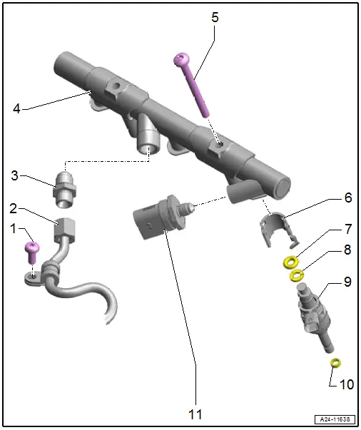
1 - Bolt
- 9 Nm
2 - High Pressure Line
- 25 Nm
- Removing and installing. Refer to → Chapter "High Pressure Pipe, Removing and Installing".
- Do not change the bending shape.
- Check for damage before reinstalling
- Counterhold the connecting pieces when loosening and tightening high pressure lines
- Coat the threads on the union nuts with fuel.
3 - Connection
- 40 Nm
- Always replace if removed
4 - Fuel Rail
5 - Bolt
- Tighten alternating from side to side in steps to 9 Nm.
6 - Support Ring
- Replace after removing
- Check for proper seating
- The strength of the support ring allows the fuel rail to hold the fuel injector tightly in the cylinder head.
7 - O-Ring
- Replace after removing
- Coat with clean engine oil
8 - Spacer Ring
- Replace if damaged
9 - Fuel Injector
- Removing and installing. Refer to → Chapter "Fuel Injectors, Removing and Installing, FSI Fuel Injection".
10 - Combustion Chamber Seal
- Replace after removing. Refer to → Chapter "Fuel Injectors, Removing and Installing, FSI Fuel Injection".
- Do not grease or treat with any other lubricants
11 - Fuel Pressure Sensor -G247-
- 25 Nm
- Removing and installing. Refer to → Chapter "Fuel Pressure Sensor -G247-, Removing and Installing".
- Coat the threads with clean engine oil.
Fuel Rail, Removing and Installing
 Caution
This procedure contains mandatory replaceable parts. Refer to component overview prior to starting procedure.
Mandatory Replacement Parts
- O-ring - Fuel injector
- Support Ring - Fuel injector
 Note
Note
Removing and installing for cylinder bank 2 (left) is described.
Removing
- Remove the supercharger. Refer to → Chapter "Supercharger, Removing and Installing".
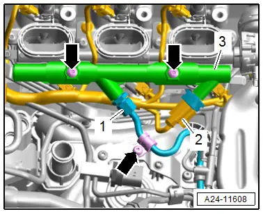
- Disconnect the connector -2-.
 WARNING
The fuel system is under pressure.
Risk of injury from fuel spraying out.
- Wear protective eyewear.
- Wear safety gloves.
- Reduce the pressure: place clean cloths around the connection point and carefully open the connection point.
- Remove the union nut -1- and bolts -arrows- and remove the fuel rail -3- from the fuel injectors at the same time pay attention to the high pressure pipe.
 Note
Note
If a fuel injector is stuck in the fuel rail disconnect the connectors.
Installing
Install in reverse order of removal and note the following:
 Note
Note
- Replace the O-rings after removing them.
- If the connection -item 3- was loosened or removed, it must be replaced.
- Install the supercharger. Refer to → Chapter "Supercharger, Removing and Installing".
Tightening Specifications
- Refer to → Chapter "Overview - Fuel Rail with Fuel Injectors"
Fuel Injectors, Removing and Installing
Fuel Injectors, Removing and Installing, MPI-Fuel Injection
 Caution
This procedure contains mandatory replaceable parts. Refer to component overview prior to starting procedure.
Mandatory Replacement Parts
- O-ring - Fuel injector
- Support Ring - Fuel injector
- Seal - Combustion chamber seal
 Note
Note
Removing and installing for cylinder bank 1 (right) is described.
Removing
- Remove the supercharger. Refer to → Chapter "Supercharger, Removing and Installing".
- Free up the fuel hose -1-.
- Disconnect the connectors -4-.
- Loosen the clamp -2- and remove the fuel hose.
- Remove the bolts -arrow- and remove the fuel rail with the fuel injectors from the intake manifold lower section.
 Note
Note
Ignore -3-.
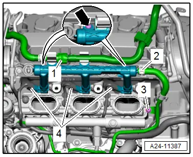
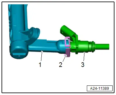
- Remove the clamp -2- and remove the fuel injector -3- from the fuel rail -1-.
Installing
Install in reverse order of removal and note the following:
 Note
Note
- Replace the O-rings after removing them.
- Secure all hose connections with hose clamps that match the ones used in series production. Refer to the Parts Catalog.
- Install the supercharger. Refer to → Chapter "Supercharger, Removing and Installing".
Tightening Specifications
- Refer to → Chapter "Overview - Fuel Rail with Fuel Injectors"
Fuel Injectors, Removing and Installing, FSI Fuel Injection
 Caution
This procedure contains mandatory replaceable parts. Refer to component overview prior to starting procedure.
Mandatory Replacement Parts
- O-ring - Fuel injector
- Support Ring - Fuel injector
- Seal - Combustion chamber seal
Special tools and workshop equipment required
- Injector/Combustion Chamber Seal Tool Set -T10133C-
Removing
- Remove the corresponding fuel rail. Refer to → Chapter "Fuel Rail, Removing and Installing".
Removing Inserted Fuel Injectors from the Fuel Rail:
- Carefully remove the fuel injectors from the fuel rail.
Removing Inserted Fuel Injectors from the Cylinder Head:
- Cover the open intake channels with a clean cloth.
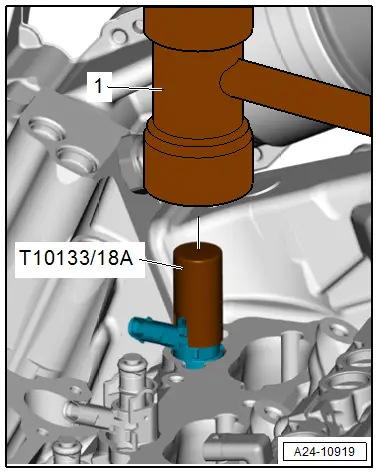
- Disconnect the connectors on the Fuel Injector that is going to be removed, and remove the Support Ring.
- Slide the Injector/Combustion Chamber Seal Tool Set - 18A -T10133/18A- over the fuel injector.
- To loosen the fuel Injector carefully tap on the sleeve.
 Note
Note
- Use a torque wrench to remove the fuel injector.
- Set the torque wrench to 5 Nm.
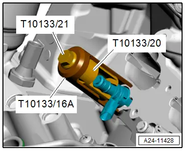
- Guide the Injector/Combustion Chamber Seal Tool Set - Puller -T10133/20- in the groove on the fuel injector.
- Install the removal tool Injector/Combustion Chamber Seal Tool Set - 16A -T10133/16A-.
- Remove the fuel injector by using a torque wrench to turn the bolt.
- If the tightening specification limit of "5 Nm" is achieved without the fuel injector loosening, remove the puller and loosen the fuel injector with the sleeve.
 Note
Note
- The fuel injectors may be damaged if the tightening specifications are not observed.
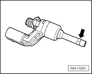
- The combustion chamber seal must be replaced before reinstalling the fuel injector.
- Carefully remove the old combustion chamber seal -arrow- by cutting the combustion chamber seal with a knife or prying it open with a small screwdriver and removing it toward the front.
 Note
Note
Make sure that the groove of the fuel injector does not become damaged. If the groove is damaged, the fuel injector must be replaced.
Installing
 Note
Note
- Use the complete repair kit when installing.
- Support ring, replacing.
- Replace the combustion chamber seal before reinstalling the fuel injector.
- Apply a thin layer of clean engine oil on the fuel injector O-rings.
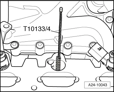
- Clean off any combustion residue on the seal groove and on the fuel injector shaft with a clean cloth before installing the new combustion chamber seal.
- Clean the hole in the cylinder head with a Nylon Cylinder Brush -T10133/4-.
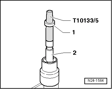
- Place the Assembly Cone -T10133/5- with new combustion chamber seal -1- from the repair kit onto the fuel injector -2-.
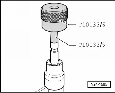
- Slide the combustion chamber seal with the Assembly Sleeve -T10133/6- onto the Assembly Cone -T10133/5- as far as possible.
- Turn the Assembly Sleeve -T10133/6- and slide the combustion chamber seal into the seal groove.
 Note
Note
When pushing the combustion chamber seal onto the fuel injector, the seal spreads open. After pushing it on, it must be tightened again in two steps, as described in the following.
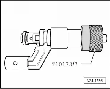
- Press the Calibration Sleeve -T10133/7- with a gentle turning movement (approximately 180º) all the way onto the fuel injector.
- Pull off the Calibration Sleeve -T10133/7- again using turning motion in opposite direction.
- Press the Calibration Sleeve -T10133/8- with a gentle turning movement (approximately 180º) all the way onto the fuel injector.
- Pull off Calibration Sleeve -T10133/8- again using turning motion in opposite direction.
- Coat the new O-ring with clean engine oil before installing it. This makes it easier to insert the fuel injector into the fuel rail.
 Note
Note
The combustion chamber seal must not be oiled.

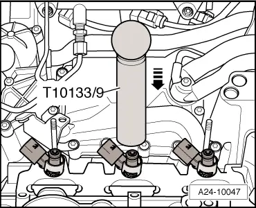
- Insert the fuel injector all the way into the hole in the cylinder head using the Assembly Mandrel -T10133/9-; when doing this, note the installation position.
- The electrical connection of the fuel injector must engage in the intended opening in the cylinder head.
 Note
Note
The fuel injector must not be difficult to install. If necessary, wait as the combustion chamber seal continues to pull itself together.
Install in reverse order of removal, note the following:
- Install the fuel rail. Refer to → Chapter "Fuel Rail, Removing and Installing".
Fuel Injectors, Cleaning
Special tools and workshop equipment required
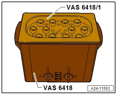
- Ultrasonic Cleaning Unit -VAS6418-
- Ultrasonic Cleaning Unit - Mounting Plate for Injection Modules -VAS6418/1-
- Ultrasonic Cleaning Unit - Cleaning Fluid -VAS6418/2-
Cleaning
- Remove the fuel injectors. Refer to → Chapter "Fuel Injectors, Removing and Installing, FSI Fuel Injection".
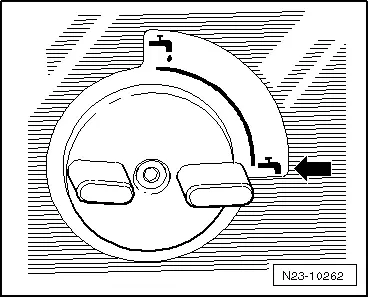
- Connect the drain valve -arrow- of the Ultrasonic Cleaning Unit -VAS6418- to the right side of the transmission housing.
- Fill the ultrasonic unit with 2120 ml (2.25 quarts) settled tap water (no air bubbles) or distilled water and Cleaning Fluid -VAS6418/2-.
Cleaning Fluid Mixture Ratio
- 2100 ml (2.2 quarts) settled tap water (no air bubbles) or distilled water and 20 ml (0.68 ounce)Cleaning Fluid -VAS6418/2-.
- Place the Mounting Plate for Injection Modules VAS6418/1 -VAS6418/1- on the cleaning unit.
 WARNING
Before operating the Ultrasonic Cleaning Unit -VAS6418- pay attention to the safety precautions in the Owner's Manual.
The ideal fluid level is reached when the cleaning fluid is approximately 1-4 mm above the bottom of the mounting plate. A fluid level which is too low can damage the Ultrasonic Cleaning Unit -VAS6418-.
- Insert the FSI fuel injectors all the way into the guides on the Mounting Plate for Injection Modules VAS6418/1 -VAS6418/1-.
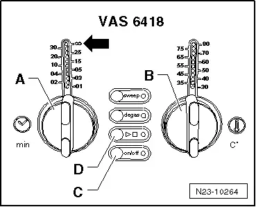
- Switch on the cleaning unit by pressing the on/off button -C-.
- Set the cleaning time on the knob -A- to 30 minutes.
- Set the temperature on the knob -B- to 50 ºC (122 ºF).
- Press the ► button -D- to start cleaning.
 Note
Note
- The temperature controlled cleaning is now switched on. During the heating-up phase the ultrasonic switches on the cleaning fluid circulation in intervals. After reaching the pre-selected temperature the ultrasonic remains permanently switched on.
- The cleaning must take at least 30 minutes and first begins once a temperature of at least 50 ºC (122 ºF) is reached.
- Install the fuel injectors with a new combustion chamber seal. Refer to → Chapter "Fuel Injectors, Removing and Installing, FSI Fuel Injection".

