Audi Q7: Gas-Filled Strut, Removing and Installing
Removing
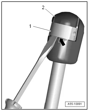
- Using a small screwdriver, lift the locking spring -1- slightly -arrow- and remove the gas-filled strut -2- from the ball pin.
- Support the lid or secure it against falling.
Installing
Install in reverse order of removal and note the following:
- Press the gas-filled strut onto the ball stud until it engages audibly.
Gas-Filled Strut, Venting
Procedure
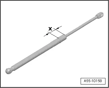
- Clamp the gas-filled strut in a vise in the area -x- = 50 mm.
 Caution
Risk of eye injury due to flying shavings.
Eye irritation and injury is possible.
- Wear protective eyewear.
- Saw the gas-filled strut cylinder within the first third of the overall cylinder length, starting from the edge on the piston rod side. While doing so, cover the cut area with a cleaning cloth to absorb oil spraying out.
Latch, Removing and Installing
Removing
- Remove the rear lid lower trim panel and the latch cover. Refer to → Body Interior; Rep. Gr.70; Luggage Compartment Trim Panels; Rear Lid Lower Trim Panel, Removing and Installing.
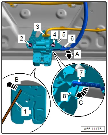
- Turn the cable at the lever -6- 90º in the -direction of the arrow A- and remove it from the cable bracket -5-.
- Using a screwdriver -1-, secure the operating lever -8- on the opposite side -arrow B-.
- Disengage the cable nipple -7- on the operating lever -arrow C-.
- Disconnect the connector -3-.
- Remove the nuts -2 and 4-.
- Remove the latch -5-.
Installing
Install in reverse order of removal.
Tightening Specifications
- Refer to → Chapter "Overview - Rear Lid"
Striker, Removing and Installing
Removing
- Remove the lock carrier trim panel. Refer to → Body Interior; Rep. Gr.70; Luggage Compartment Trim Panels; Lock Carrier Trim Panel, Removing and Installing.
- Mark the installation position for reinstallation.
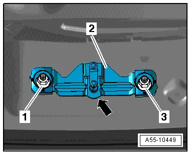
- Remove the nuts -1 and 3- and remove the striker -2-.
Installing
Install in reverse order of removal and note the following:
- Insert the striker on the correct side.
- The round side -arrow- on the striker faces upward.
- Adjust the striker. Refer to → Chapter "Height Adjustment at Striker".
Tightening Specifications
- Refer to → Chapter "Overview - Rear Lid"
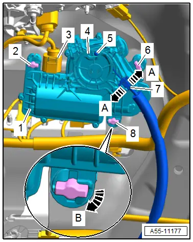
Rear Lid Closing Assist Motor -V382-, Removing and Installing
Removing
- Remove the rear lid lower trim panel. Refer to → Body Interior; Rep. Gr.70; Luggage Compartment Trim Panels; Rear Lid Lower Trim Panel, Removing and Installing.
- Disengage the cable bracket -7- to do so release the catches -A arrows-.
- Disengage the cable nipple -5- on the operating lever -4-.
- Disconnect the connector -3-.
- Release the catches -2, 6 and 8- 90º clockwise -arrow B-.
- Remove the Rear Lid Closing Assist Motor -V382--item 1-.
Installing
Install in reverse order of removal.
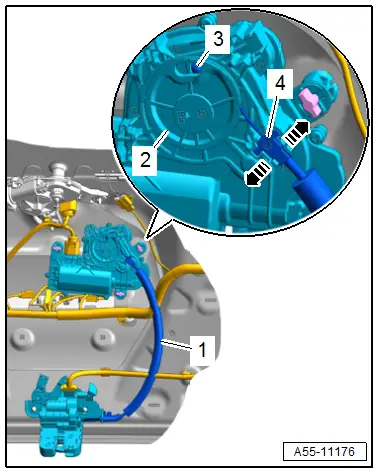
Closing Assist Release Cable, Removing and Installing
Removing
- Remove the rear lid lower trim panel and the latch cover. Refer to → Body Interior; Rep. Gr.70; Luggage Compartment Trim Panels; Rear Lid Lower Trim Panel, Removing and Installing.
- Turn the operating cable on the lever -3- 90º in the -direction of arrow A- and remove it from the cable bracket -2-.
- Using a screwdriver -1-, secure the operating lever -5- on the opposite side -arrow B-.
- Disengage the cable nipple -4- on the operating lever -arrow C-.

- Disengage the cable bracket -4- on the Rear Lid Closing Assist Motor - V382- to do so release the catches -arrows-.
- Disengage the cable nipple -3- on the operating cable -2-.
- Remove the cable -1-.
Installing
Install in reverse order of removal.

