Audi Q7: Rear Lid Drive Unit -VX69-, Removing and Installing
 Caution
This procedure contains mandatory replaceable parts. Refer to component overview prior to starting procedure.
Removing
- Remove the D-pillar trim panel. Refer to → Body Interior; Rep. Gr.70; Vehicle Interior Trim Panels; D-Pillar Trim Panel, Removing and Installing.
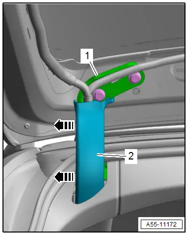
- Release the catches -arrows- and remove the cover -2- from the hinge -1-.
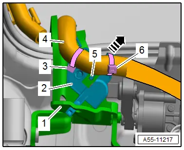
- Cut through the cable ties -3 and 6- and free up the wiring harness -4-.
- Release the catch -5- and remove the cover -2- from the mount -1--arrow-.
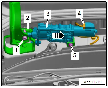
- Remove the bolts -1 and 5-.
- Remove the rear lid motor -3- from the mount on the hinge -2--arrow-.
- Disconnect the connector -4-.
Installing
Install in reverse order of removal and note the following:
- The connector must be connected before inserting the rear lid motor.
- Perform an adaptation.
Rear Lid Drive Unit -VX69-, Adapting
- Connect the Vehicle Diagnostic Tester.
- Switch the ignition on.
- Select and start the Diagnostic operating mode.
- Select the Test plan tab.
- Select the Select individual test button and select the following tree structure consecutively:
- Body
- Body Assembly
- 01 - OBD-capable systems
- 6D - Rear Lid Electronics, J605
- 6D - Rear Lid Control Module, Functions
- 6D - Basic setting, Rear Lid Control Module
- Start the selected program and follow the instructions on the Vehicle Diagnostic Tester display.
Tightening Specifications
- Refer to → Chapter "Overview - Electric Rear Lid Release"
Rear Lid Control Module -J605-, Removing and Installing
Removing
- Remove the roof end strip. Refer to → Body Interior; Rep. Gr.70; Roof Trim Panels; Roof End Strip, Removing and Installing.
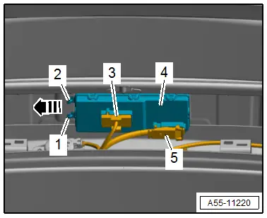
- Disconnect the connectors -3 and 5-.
- Release the catches -1 and 2- and at the same time push the control module -4- to the left side -arrow-. Doing so disengages the brackets from the guides.
- Remove the Rear Lid Control Module -J605-.
Installing
Install in reverse order of removal and note the following:
- Insert the control module and push it to the right until the catches engage audibly.
Rear Lid Opener Control Module -J938-, Removing and Installing
Removing
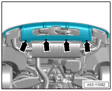
- Remove the bolts -arrows- on the lower section of the bumper cover.
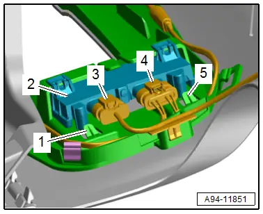
- Disconnect the connectors -3 and 4-.
- Release the catches -1 and 5-.
- Remove the control module -2- from the mount.
Installing
Install in reverse order of removal.
Tightening Specifications
- Refer to → Chapter "Overview - Bumper Cover"
Power Rear Lid Opener Sensors -G750-/-G760-, Removing and Installing
Removing
- Remove the bolts -arrows- on the lower section of the bumper cover.

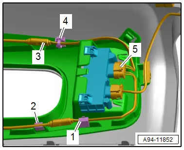
- Disconnect the connector -5-.
- Free up the sensor -3- by cutting through the cable tie -4-.
- Remove the sensor -2- from the clamps -1-.
Installing
Install in reverse order of removal and note the following:
- The Rear Lid Opener Sensor 2 -G760- must be secured on the upper bumper cover. Identifying feature: Pin 4" and 5" on the connector.
Tightening Specifications
- Refer to → Chapter "Overview - Bumper Cover"

