Audi Q7: Generator
Overview - Generator
Overview - Generator without Bushing, Vehicles with 6-Cylinder Engine
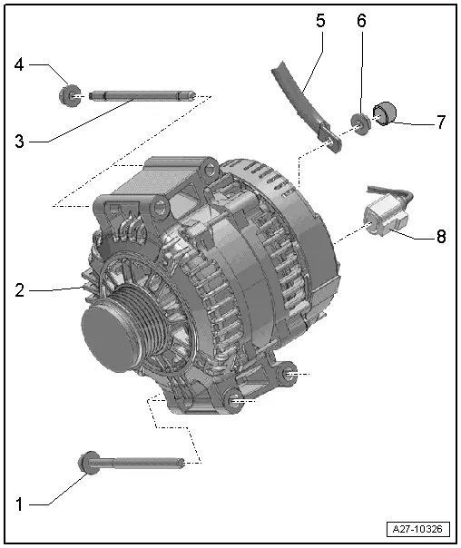
1 - Bolt
- 20 Nm
- Quantity: 2
2 - Generator
- Removing and installing. Refer to → Chapter "Generator, Removing and Installing".
3 - Threaded Pin
- 10 Nm
- Quantity: 2
4 - Nut
- 20 Nm
- Quantity: 2
5 - Terminal 30/B+
6 - Nut
- 16 Nm
7 - Cap
8 - Connector
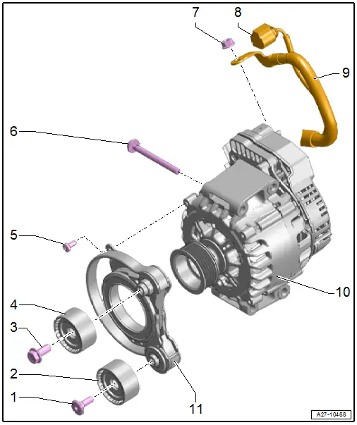
Overview - Generator with Bushings

1 - Bolts
- 23 Nm
2 - Generator
- Removing and installing. Refer to → Chapter "Generator, Removing and Installing".
3 - Bushing
- Tight generator mount bushings must be loosened, otherwise the clamping force of the sleeve is too little despite the correct torque.
4 - Connector
5 - Nut
- 16 Nm
6 - Cap
7 - Terminal 30/B+
Overview - Generator, Starter Generator -C29-, Vehicles with High-Voltage System and 6-Cylinder TDI Engine
1 - Bolt
- 30 Nm
2 - Idler Roller
3 - Bolt
- 30 Nm
- Left-hand thread
4 - Idler Roller
5 - Bolt
- 15 Nm
- Quantity: 4
6 - Bolt
- 20 Nm
- Quantity: 4
7 - Nut
- 18 Nm
8 - Connector
9 - 30/B+ Terminal
10 - Starter Generator -C29-
- Removing and installing. Refer to → Chapter "Generator, Removing and Installing, Starter Generator -C29-, Vehicles with High-Voltage System and 6-Cylinder TDI Engine".
11 - Tensioner
- For Starter Generator -C29-
- Removing and installing. Refer to → Chapter "Tensioner for Starter Generator -C29-, Removing and Installing".
Generator, Removing and Installing
Generator, Removing and Installing, Vehicles with 3.0L TFSI Engine
Special tools and workshop equipment required
- 12 edged 5 mm socket, commercially available
Removing
- During installation, all cable ties must be installed at the same location.
- Turn off the ignition and disconnect the ground cable from the battery. Refer to → Chapter "Battery, Disconnecting and Connecting".
- Remove the ribbed belt for the A/C compressor. Refer to → 6-Cylinder Direct Injection 3.0L 4V TFSI Supercharged Engine; Rep. Gr.13; Cylinder Block, Belt Pulley Side; Ribbed Belt, Removing and Installing.
- Release the tension on the ribbed belt and remove it from the generator pulley. Refer to → 6-Cylinder Direct Injection 3.0L 4V TFSI Supercharged Engine; Rep. Gr.13; Cylinder Block, Belt Pulley Side; Ribbed Belt, Removing and Installing.
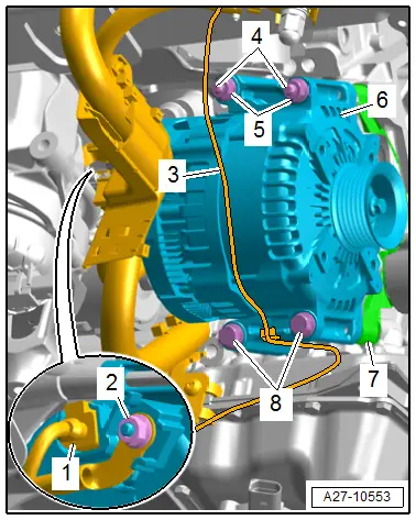
- Free up the wiring harness -3- on the generator -6-.
- Loosen the nuts -5- and threaded pin -4- with a 12 edge 5 mm socket.
- Remove the bolts -8- and the bracket for the generator -7-.
- Remove the nut -2- and free up the B+ wire.
- Disconnect the connector -1-.
- Remove the generator downward.
Installing
Install in the reverse order of removal while noting the following:
- Make sure the ribbed belt is on securely and is routed correctly.
- Connect the battery. Required actions.
- Start the engine and check the ribbed belt routing.
Tightening Specifications
- Refer to → Chapter "Overview - Generator without Bushing, Vehicles with 6-Cylinder Engine"
Generator, Removing and Installing, Vehicles with 3.0L TDI Engine
Removing
- Turn off the ignition and disconnect the ground cable from the battery. Refer to → Chapter "Battery, Disconnecting and Connecting".
- Remove the right lower longitudinal member. Refer to → Body Exterior; Rep. Gr.50; Lock Carrier; Overview - Lock Carrier.
- Release the tension on the ribbed belt and remove it from the generator pulley. Refer to → 6-Cylinder Direct Injection 3.0L 4V TFSI Supercharged Engine; Rep. Gr.13; Cylinder Block, Belt Pulley Side; Ribbed Belt, Removing and Installing.
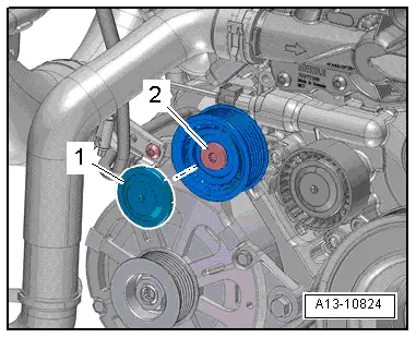
- Unclip the cover -1-.
- Remove the bolt -2- and the right idler roller.
- Remove the air duct pipe bolt -2-.
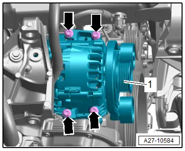
- Loosen the bolts -arrows- for the generator -1- about six turns.
- To loosen the bushings of the generator mount use a hammer and carefully tap on the bolt heads.
- Remove the bolts completely.
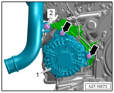
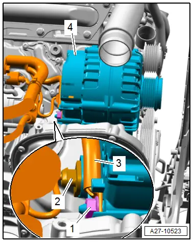
- Remove the generator -4- from the bracket.
- Remove the nut -1- and the B+ wire -3-.
- Disconnect the connector -2-.
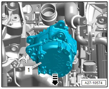
- Remove the generator -1- in direction of -arrow-, as shown.
Installing
Install in the reverse order of removal while noting the following:
- Drive the bolt bushings back slightly to make it easier to install the generator.
- Tight generator mount bushings must be loosened, otherwise the clamping force of the sleeve is too little despite the correct torque.
- Connect the battery. Required actions.
- Start the engine and check the ribbed belt routing.
Tightening Specifications
- Refer to → Chapter "Overview - Generator with Bushings"
- Refer to → Body Exterior; Rep. Gr.50; Lock Carrier; Overview - Lock Carrier.
Generator, Removing and Installing, Starter Generator -C29-, Vehicles with High-Voltage System and 6-Cylinder TDI Engine
Removing
- Disconnect the ground cable from the battery when the ignition is switched off. Refer to → Chapter "Battery, Disconnecting and Connecting".
- Remove the right lower longitudinal member. Refer to → Body Exterior; Rep. Gr.50; Lock Carrier; Overview - Lock Carrier.
- Remove the fan shroud. Refer to → Engine Mechanical; Rep. Gr.19; Radiator/Radiator Fan; Fan Shroud, Removing and Installing.
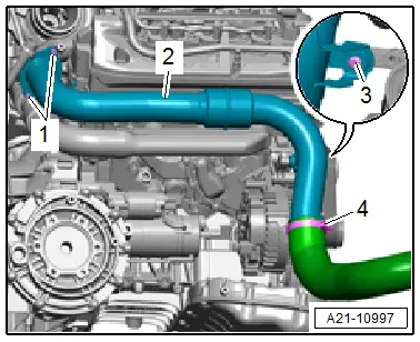
- Loosen the hose clamp -4- and remove the air duct hose.
- Remove the bolts -1 and 3- and push the air duct pipe -2- slightly upward.
- Release the tension on the ribbed belt and remove it from the starter generator-belt pulley. Refer to → Engine Mechanical; Rep. Gr.13; Belt Pulley Side Cylinder Block; Ribbed Belt, Removing and Installing.
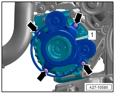
- Remove the bolts -arrows- and pull the starter generator -1- slightly forward.
- Remove the nut -3- and free up the B+ wire -1-.
- Disconnect the connector -2-.
- Remove the starter generator downward.

Installing
Install in reverse order of removal and note the following:
- Make sure the ribbed belt is on securely and is routed correctly.
- Connect the battery. Required actions.
- Start the engine and check the ribbed belt routing.
Tightening Specifications
- Refer to → Chapter "Overview - Generator, Starter Generator -C29-, Vehicles with High-Voltage System and 6-Cylinder TDI Engine"
- Refer to → Body Exterior; Rep. Gr.50; Lock Carrier; Overview - Lock Carrier.
Tensioner for Starter Generator -C29-, Removing and Installing
Removing
- Release the tension on the ribbed belt and remove it from the starter generator-belt pulley. Refer to → Engine Mechanical; Rep. Gr.13; Belt Pulley Side Cylinder Block; Ribbed Belt, Removing and Installing.
- Remove the bolts -arrows-.
- Remove the tensioner -1-.
Installing
Install in reverse order of removal and note the following:
- Make sure the ribbed belt is on securely and is routed correctly.
- Start the engine and check the ribbed belt routing.
Tightening Specifications
- Refer to → Chapter "Overview - Generator, Starter Generator -C29-, Vehicles with High-Voltage System and 6-Cylinder TDI Engine"

