Audi Q7: Fuel Delivery Unit/Fuel Level Sensor
Overview - Fuel Delivery Unit/Fuel Level Sensor
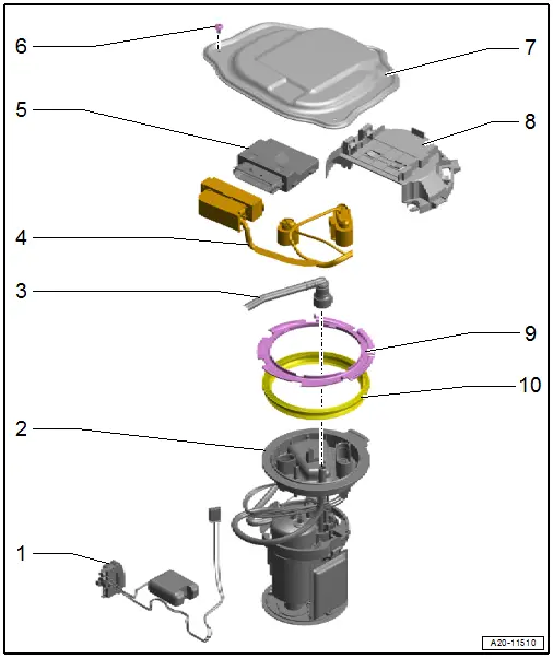
1 - Fuel Level Sensor
- Use the Vehicle Diagnostic Tester to check the Fuel Level Sensor -G- and Fuel Level Sensor 2 -G169-
- Fuel Level Sensor -G-, removing and installing. Refer to → Chapter "Fuel Level Sensor -G-, Removing and Installing".
 Note
Note
The Fuel Level Sensor 2 -G169- is integrated in the fuel tank and cannot be replaced separately.
2 - Fuel Delivery Unit
- With the Transfer Fuel Pump -G6-
- With integrated fuel filter, the fuel filter cannot be replaced individually
- Check the fuel pump electronically using the Vehicle Diagnostic Tester.
- Refer to → Chapter "Fuel Delivery Unit/Fuel Level Sensor, Removing and Installing".
- Fill the vehicle with at least five liters (1.32 gallons) of fuel after installing
3 - Fuel Line
- To the engine
- Do not kink
- Connector couplings, separating and connecting. Refer to → Chapter "Connector Couplings, Disconnecting".
4 - Wiring Harness
- For Fuel Pump Control Module -J538-, Transfer Fuel Pump -G6-, Fuel Level Sensor -G- and Fuel Level Sensor 2 -G169-
- Make sure it is attached securely
5 - Fuel Pump Control Module -J538-
- Check using the Vehicle Diagnostic Tester.
- Refer to → Chapter "Fuel Pump Control Module -J538-, Removing and Installing".
6 - Bolt
- 1.5 Nm
- Quantity: 3
7 - Sealing Flange Cover
8 - Bracket
- For Fuel Pump Control Module -J538-
9 - Locking Ring
- 110 Nm
- Loosen and tighten using the Wrench - Fuel Sending Unit -T10202-
10 - Gasket
- Replace after removing
- Install dry
Fuel Delivery Unit/Fuel Level Sensor, Removing and Installing
Special tools and workshop equipment required
- Wrench - Fuel Sending Unit -T10202-
- Safety Gloves
Removing
- Observe the safety precautions. Refer to → Chapter "Safety Precautions".
- Follow the guidelines for clean working conditions. Refer to → Chapter "Guidelines for Clean Working Conditions".
 WARNING
Danger due to escaping fuel.
To prevent large quantities of fuel from leaking from the fuel delivery unit when removing, the fuel tank may only be a maximum of 1/4 full.
- If required, drain the fuel tank. Refer to → Chapter "Fuel Tank, Draining".
 Caution
Risk of destroying electronic components when disconnecting the battery.
Follow the steps for disconnecting the battery.
- Disconnect the ground cable from the battery terminal. Refer to → Electrical Equipment; Rep. Gr.27; Battery; Battery, Disconnecting and Connecting.
- Move the front seats all the way forward into the highest position.
- Remove the right rear and front sill panel. Refer to → Body Interior; Rep. Gr.70; Vehicle Interior Trim Panels; Sill Panel, Removing and Installing.
- Remove the bench seat/right and center single seats. Refer to → Body Interior; Rep. Gr.72; Rear Seats; Bench Seat/Single Seat, Removing and Installing.
- Remove the support for the right luggage compartment floor. Refer to → Body Interior; Rep. Gr.70; Luggage Compartment Trim Panels; Overview - Luggage Compartment Floor.
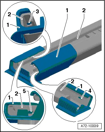
- Remove the cover -1- on the front passenger seat behind both seat rails, to do so release the tabs -3, 4 and 5- carefully on the seat rail -2-.
 Note
Note
The front passenger seat does not need to be removed.
- Remove the carpet under the seat rail.
- Remove the cover and connector station for the bench seat / single seat in the carpet.
- Fold the carpet near the sealing flange cover to the side.
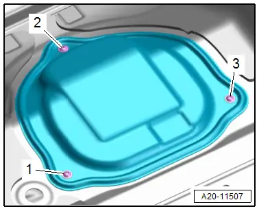
- Remove the bolts -1, 2 and 3- and remove the sealing flange cover.
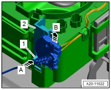
- Release the catches -arrows- using a screwdriver and remove the Fuel Pump Control Module -J538--1- from the bracket.
- Release the connector safety catch and disconnect the connector -2- for the Fuel Pump Control Module -J538-.
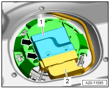
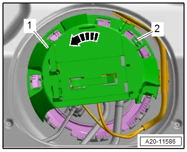
- Release the catch -2- with a screwdriver and turn the bracket -1- for the Fuel Pump Control Module -J538- counter-clockwise in direction of -arrow-.
- Disengage the bracket on the locking ring and remove.
- Disconnect the connectors -1 and 2- on the sealing flange by releasing the connector safety catch.
 WARNING
The fuel system is under pressure.
Risk of injury from fuel spraying out.
- Wear protective eyewear.
- Wear safety gloves.
- Reduce the pressure: place clean cloths around the connection point and carefully open the connection point.
- Remove the fuel line -2- from the sealing flange. Disconnect the connector couplings. Refer to → Chapter "Connector Couplings, Disconnecting".
 WARNING
Danger due to escaping fuel.
To prevent large quantities of fuel from leaking from the fuel delivery unit when removing, the fuel tank may only be a maximum of 1/4 full.
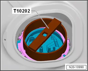
- Remove the locking ring using the Wrench - Fuel Sending Unit -T10202-.

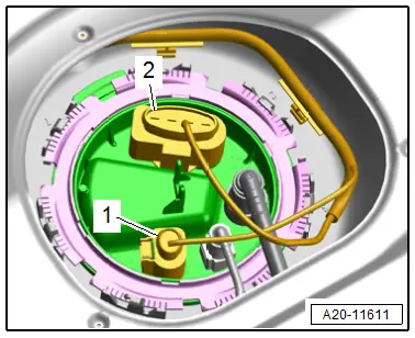
- Pull the sealing flange -1- just slightly out of the opening in the fuel tank and remove the gasket -2-.
- Carefully pull the sealing flange with the fuel lines out of the fuel tank opening.
- Release the connector safety catch and disconnect the connectors from the sealing flange.
1 - For Fuel Level Sensor -G-
2 - For Fuel Level Sensor 2 -G169-
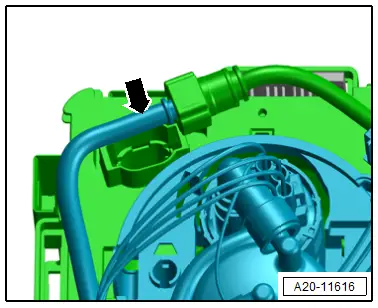
Suction Jet Line Version 1
- Reach through the opening in the fuel tank and disconnect the suction jet line -arrow-. Disconnect the connector couplings. Refer to → Chapter "Connector Couplings, Disconnecting".
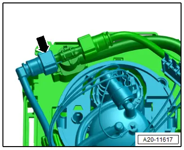
Suction Jet Line Version 2
- Reach through the opening in the fuel tank and disconnect the suction jet line -arrow-. Disconnect the connector couplings. Refer to → Chapter "Connector Couplings, Disconnecting".
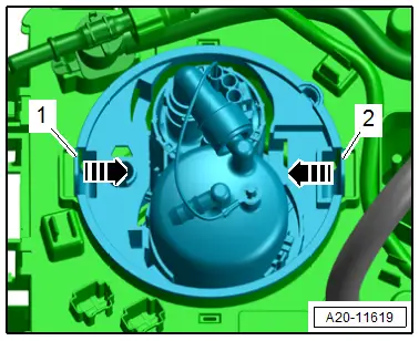
Continuation for All Vehicles
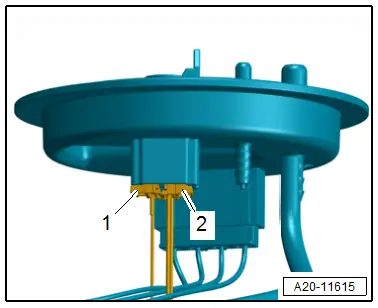
- Reach through the opening in the fuel tank, push the catches -1 and 2- one after the other in the direction of -arrow- and at the same time release the fuel delivery unit.
 WARNING
There is a risk of fuel leaking out from the filled fuel delivery unit.
Lay cloths below to catch the leaking fuel.
- Carefully remove the fuel delivery unit from the fuel tank opening.
 Note
Note
For clarity the fuel delivery unit is shown without the fuel supply line.
Installing
Install in reverse order of removal and note the following:
 Note
Note
- Replace the gasket after removal.
- Check the fuel delivery unit for secure fit.
- Carefully guide the fuel delivery unit into the fuel tank.
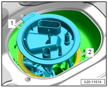
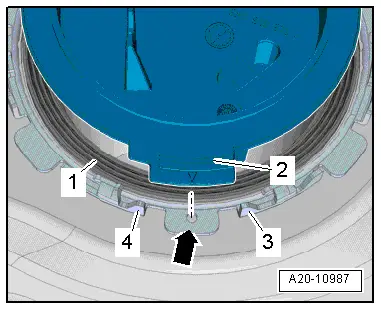
- Reach through the opening in the fuel tank and move the fuel delivery unit into its installation position.
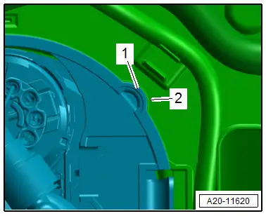
- The tab -1- on the fuel delivery unit must be in the groove on the baffle housing -2-.
- Push the fuel delivery unit downward until it engages audibly in the catches on the baffle housing.
- Push the fuel delivery unit again and pull on it to check if the catches -1 and 2- are engaged correctly.
- Reach in the fuel tank installation opening and connect the suction jet line on the fuel delivery unit until it clicks into place.
 Note
Note
Ignore the -arrows-.

- Connect the connectors -1 and 2- and make sure they are securely locked.

- Install the new sealing flange seal -1-. The seal must be dry.
 Caution
Risk of leaking.
When inserting the sealing flange, the seal must not be damaged or crushed.
- Set the sealing flange into the installation position.
- The tab -2- on the sealing flange must face the hole -arrow- in the locking ring and be between the tabs -3 and 4- on the fuel tank.
- Press on the sealing flange securely and tighten using the Wrench - Fuel Sending Unit -T10202-.
- Attach the fuel lines until they engage audibly.
- Connect the connectors and make sure they are secure.
- After installing the fuel delivery unit, fill the fuel tank with at least five liters (1.32 gallons) of fuel.
 Note
Note
Do not allow the fuel pump to run when the fuel tank is empty.
- Install the support for the luggage compartment floor. Refer to → Body Interior; Rep. Gr.70; Luggage Compartment Trim Panels; Overview - Luggage Compartment Floor.
- Install the bench seat / single seat. Refer to → Body Interior; Rep. Gr.72; Rear Seats; Bench Seat/Single Seat, Removing and Installing.
- Install the sill panel. Refer to → Body Interior; Rep. Gr.70; Vehicle Interior Trim Panels; Sill Panel, Removing and Installing.
- Connect the battery. At the same time, follow all steps after connecting the battery. Refer to → Electrical Equipment; Rep. Gr.27; Battery; Battery, Disconnecting and Connecting.
Tightening Specifications
- Refer to → Chapter "Overview - Fuel Delivery Unit/Fuel Level Sensor"
Fuel Level Sensor -G-, Removing and Installing
Removing
- Follow all safety precautions. Refer to → Chapter "Safety Precautions".
- Follow the guidelines for clean working conditions. Refer to → Chapter "Guidelines for Clean Working Conditions".
- Remove the fuel delivery unit. Refer to → Chapter "Fuel Delivery Unit/Fuel Level Sensor, Removing and Installing".
- Free up the wire for the Fuel Level Sensor -G- on the baffle housing.
- Reach through the fuel tank opening, release the catch -1- in direction of -arrow A- and at the same time remove the bracket -2- with the Fuel Level Sensor -G- from the mount on the baffle housing in direction of -arrow B-.
- Carefully remove the Fuel Level Sensor -G- from the fuel tank opening.
 Note
Note
Be careful not to bend the floater arm on the fuel level sensor when removing.
Installing
Install in reverse order of removal and note the following:
 Note
Note
Be careful not to bend the floater arm on the fuel level sensor when inserting.
- Guide the Fuel Level Sensor -G- carefully through the opening in the fuel tank.
- Insert the Fuel Level Sensor -G- into the mount on the baffle housing and push downward until it engages.
- Engage the wire on the baffle housing.
- Install the fuel delivery unit. Refer to → Chapter "Fuel Delivery Unit/Fuel Level Sensor, Removing and Installing".

