Audi Q7: Heater and A/C Unit, Removing and Installing
General Information
- Depending on vehicle equipment, there are different versions of the A/C system for the Audi Q7. Make sure to use the correct version and pay attention to the allocation of different components. Refer to → Chapter "A/C System Versions" and Parts Catalog.
- Currently in this vehicle, all actuators are identical in construction. During the basic setting, the actuators are assigned and adapted corresponding to the switching sequence of the wiring. If this sequence does not conform with the specification, the actuators will adapt incorrectly and the door control will be wrong. Refer to → Chapter "Main Wiring Diagram for A/C System Actuators".
- Therefore, perform the basic setting for the A/C system after installation of the rear air distribution housing. Refer to Vehicle Diagnostic Tester the "Guided Fault Finding" function.
- Using the "output diagnostic test mode" and "basic setting" functions, the activation of A/C system electrical components can be tested if necessary (for example, allocation test). Refer to Vehicle Diagnostic Tester in the "Guided Fault Finding" function.
- After installing a new actuator, check the activation via the Front A/C Display Control Head -E87- and the actuator function. Refer to Vehicle Diagnostic Tester in the "Guided Fault Finding" function.
Heater and A/C Unit, Removing and Installing, "Mid" or "Mix" A/C System
Removing
- Turn off the ignition.
- Remove the base support -A- of center console and insulation -B-. Refer to → Body Interior; Rep. Gr.68; Center Console; Center Console Bracket, Removing and Installing.
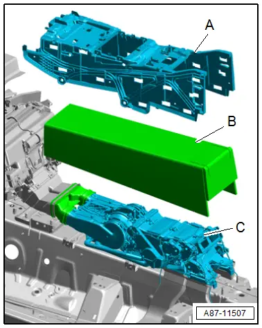
- Detach the rear air distribution housing -D- from the retaining points -A- and air ducts -E- and remove.
Installing
Install in reverse order of removal. Note the following:
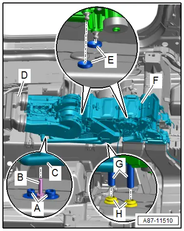
- Check the grommets -B, C, and F- for damage and proper seating.

 Note
Note
The grommets -B, C, and F- are only present in vehicles with an air distribution housing.
- Check the retaining points -A- for correct installation in the center tunnel and for damage.
- Check the ball heads on air distribution housing -D-, which are inserted in retaining points -A-, for damage.
- Check the outlets at rear air distribution housing -D-, which are inserted in air ducts -E-, and air ducts -E-, for damage and contamination.
 Note
Note
Damaged or improperly joined components can result in noises during operation of the A/C system.
- Insert the rear air distribution housing -D- into the retaining points -A- and air ducts -E-.
- Perform the basic setting and the output diagnostic test mode of the A/C system. Refer to Vehicle Diagnostic Tester in the "Guided Fault Finding" function.
 Note
Note
- In this vehicle, the actuators are equipped with electronics. During the basic setting, a new control motor learns its position on the heater and A/C unit and can then be activated by the Front A/C Display Control Head -E87- (currently all actuators are identical). Refer to Vehicle Diagnostic Tester in the "Guided Fault Finding" function.
- During the basic setting, the actuators are assigned and adapted corresponding to the switching sequence of the wiring. If this sequence does not conform with the specification, the actuators will adapt incorrectly and the door control will be wrong. Refer to → Chapter "Main Wiring Diagram for A/C System Actuators".
- Check the DTC memory on the Front A/C Display Control Head -E87- and erase any displayed malfunctions. Refer to Vehicle Diagnostic Tester in the "Guided Fault Finding" function.
Heater and A/C Unit, Removing and Installing, "High" A/C System
Special tools and workshop equipment required
- Hose Clamps - Up To 25mm -3094-
- Engine Bung Set -VAS6122-
- Container of the Coolant Collection System -VAS5014- or the Shop Crane - Drip Tray -VAS6208-
- Hose Clip Pliers -VAS6340-
Removing
- Turn off the ignition.
- Discharge the refrigerant circuit. Refer to → Refrigerant R134a Servicing; Rep. Gr.87; Refrigerant Circuit.
 WARNING
There is a risk of scalding from hot steam and coolant.
- The cooling system is under pressure when the engine is warm.
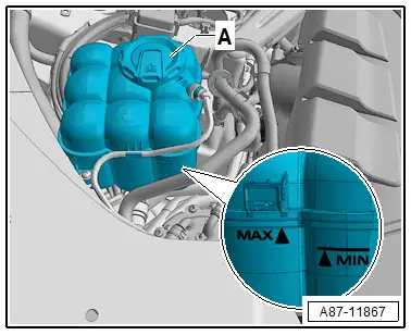
- To reduce the pressure, cover the coolant reservoir cap with cloths and then open it carefully.
- Carefully open the coolant expansion tank cap -A- (do not completely remove).
 Note
Note
There are different versions of the coolant expansion tank and in different allocations in the engine compartment. Refer to → Rep. Gr.19; Coolant System/Coolant; Coolant, Draining and Filling.
- Vehicles with 6-cylinder engine, remove the left front muffler. Refer to → Rep. Gr.26; Exhaust Pipes/Mufflers; Front Muffler, Removing and Installing.
- Place the container of the Coolant Collection System -VAS5014- or the Shop Crane - Drip Tray -VAS6208- underneath.
- Mark the layout of the coolant hoses -C and D- on the connections to the heat exchanger.
 Note
Note
- The heat exchanger is installed in the heater and A/C units so that a specific flow direction of the coolant is necessary for clean bleeding of the heater core. Therefore, the coolant hoses must be connected on the correct side. Refer to → Chapter "Incorporating the Heating and A/C System in the Coolant Circuit".
- Bleed the coolant circuit. Refer to → Chapter "Coolant Circuit, Bleeding" and → Rep. Gr.19; Coolant System/Coolant; Coolant, Draining and Filling.
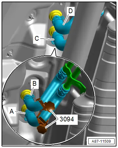
- Clamp off the coolant hoses using the Hose Clamps - Up To 25mm -3094-.
- Loosen the clamps -A and B- and remove the coolant hoses.
 Note
Note
Immediately seal off any open line connections and connection points with clean plugs, for example, taken from the Engine Bung Set -VAS6122-.
- Remove the base support -A- of center console and insulation -B-. Refer to → Body Interior; Rep. Gr.68; Center Console; Center Console Bracket, Removing and Installing.

- Clearly label the line routing to the four temperature sensors -A through D- on the air ducts.
 Caution
Interchange of the wire connections to the temperature sensors or the connectors at the adjustment motors results in problems regarding the regulation of the A/C system.
- Interchanged connectors at the adjustment motors or the temperature sensors are not identified as malfunctions by the Rear A/C Display Control Head -E265-.
- Prior to disconnecting connectors or removing electrical components, clearly label them in order to rule out confusion.
- Remove the temperature sensor -A through D- from the air ducts and secure together with the corresponding wire on the rear heater and A/C unit, so that interfere with removal of the heater and A/C unit -E- and are not damaged. Refer to → Chapter "Left/Right Rear Upper Body Vent Temperature Sensor -G635-/-G636-, Removing and Installing" and → Chapter "Left/Right Rear Footwell Vent Temperature Sensor -G637-/-G638- , Removing and Installing".
- Remove the nut -A- from the connection location of the refrigerant lines.
 Note
Note
If the operating lever -B- is awkwardly positioned so that the nut -A- is not accessible, remove the rear recirculation door motor. Refer to → Chapter "Rear Recirculation Door Motor -V421-, Removing and Installing".
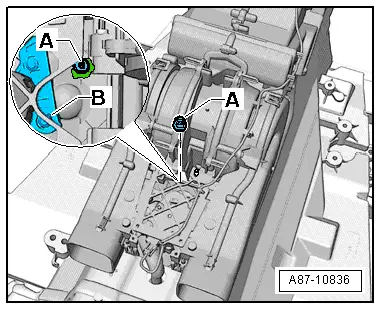
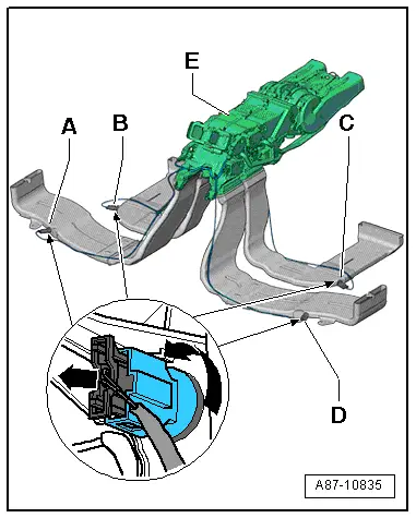
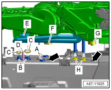
- Loosen the heater and A/C unit -C- from the retaining points -B- and the air duct -A-.
- Remove the refrigerant line connection -H- on the connection point to the refrigerant lines -F-.
- Place absorbent paper around the coolant lines -E-.
- Remove the coolant lines -E- from the heat exchanger from the grommets in the center tunnel.
- Remove the heater and A/C unit.
 Note
Note
- Refrigerant lines -H- (from the rear expansion valve through the center tunnel) and threaded stud -G- remain installed.
- When the heater and A/C unit is removed, refrigerant lines and threaded stud are held in position by a bracket which is glued in place from below in the center tunnel. Refer to → Chapter "Refrigerant Lines, Removing and Installing, from Rear Expansion Valve to Evaporator in Rear Heater and A/C Unit".
- Immediately seal off any open line connections and connection points with clean plugs, for example, taken from the Engine Bung Set -VAS6122-.
- Cover the air ducts in the rear passenger compartment so that they are not compressed or damaged during further work steps.
Installing
Install in reverse order of removal. Note the following:
 Note
Note
- Secure all hose connections with hose clamps used in standard production. Refer to the Parts Catalog.
- Used coolant cannot be used again.
- Check the grommet -H- for the coolant lines and the rubber bushing -A- for the correct seating and damage.
- Check foam seals -F and G- on the condensation water drains for damage and proper seating.
- Check the condensation water drain for damage and debris.
- Check both openings -arrows- for the condensation water drains. They must not be closed.
- The condensation water must be able to flow unobstructed out of the condensation water drain.
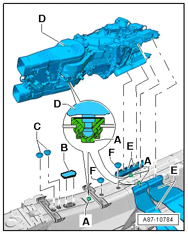
- Check the refrigerant line connection -E- and the refrigerant lines -B- for debris and damage.
 Note
Note
Even slight damage (a scratch) or a little bit of dirt (a hair) can cause leakage at a connection.
- Replace the O-ring seals -C-. Refer to the Parts Catalog for the version.
- Coat the O-ring seals lightly with refrigerant oil before installing. Refer to → Chapter "Refrigerant Circuit Seals".
- Check the retaining plate that holds refrigerant lines and threaded stud -D- in place for secure seating.
 Caution
If the rear heater and A/C unit is installed in a careless manner, the retaining plate that holds refrigerant lines -B- and the threaded stud -D- in place can detach from the vehicle.
- This retaining plate is adhered to the floor plate. If it is pressed away during installation of the rear A/C unit, attachment of the refrigerant lines may require significant extra work. Refer to → Chapter "Refrigerant Lines, Removing and Installing, from Rear Expansion Valve to Evaporator in Rear Heater and A/C Unit".
- Pay particular attention to this connection when installing the rear heater and A/C unit and work carefully.
 Note
Note
- Grommets -B, C, and F- are only present in vehicles with an air distribution housing. They may not be installed in vehicles with a rear heater and A/C unit.
- If a grommet -F- is installed in one of the two openings for the condensation water drains in a vehicle with a rear heater and A/C unit or if these opening are closed from the bottom, for example by underbody sealant, condensation water cannot flow out of the vehicle. Refer to → Chapter "Condensation Water Drain Hose, Checking".
- Check the ball heads on rear heater and A/C unit -D-, which are inserted in holding points -A-, for damage.
- Check the outlets at rear heater and A/C unit -D-, which are inserted in air ducts -E-, and air ducts -E-, for damage and contamination.
 Note
Note
Damaged or improperly joined components can result in noises during operation of the A/C system.
- Evacuate and charge the refrigerant circuit. Refer to → Refrigerant R134a Servicing; Rep. Gr.87; Refrigerant Circuit.
- Perform the basic setting and the output diagnostic test mode of the A/C system. Refer to Vehicle Diagnostic Tester in the "Guided Fault Finding" function.
 Note
Note
- In this vehicle, the actuators are equipped with electronics. During the basic setting, a new actuator learns its position on the heater and A/C unit and can then be activated by the Rear A/C Display Control Head -E265- / the Front A/C Display Control Head -E87- (currently all actuators are identical). Refer to Vehicle Diagnostic Tester in the "Guided Fault Finding" function.
- During the basic setting, the actuators are assigned and adapted corresponding to the switching sequence of the wiring. If this sequence does not conform with the specification, the actuators will adapt incorrectly and the door control will be wrong. Refer to → Chapter "Main Wiring Diagram for A/C System Actuators".
- Check the coolant circuit to the heater core in the rear heater and A/C unit. Refer to → Chapter "Coolant Circuit, Bleeding".
- Check the DTC memory of the Front A/C Display Control Head -E87- (and the Rear A/C Display Control Head -E265-) and if necessary erase any malfunctions shown. Refer to Vehicle Diagnostic Tester in the "Guided Fault Finding" function.
- Operate the A/C system after charging the refrigerant circuit. Refer to → Chapter "A/C System, Starting after Charging Refrigerant Circuit".
 Note
Note
Note the information regarding operating the A/C system after filling. Refer to → Refrigerant R134a Servicing; Rep. Gr.87; A/C System, General Information.
- Check the functionality of the A/C system. Refer to Vehicle Diagnostic Tester in the "Guided Fault Finding" function.

