Audi Q7: Rear Upper Body Vent Temperature Sensor -G537-, Removing and Installing
Rear Upper Body Vent Temperature Sensor -G537-, Removing and Installing, "Low" A/C System
 Note
Note
The Rear Upper Body Vent Temperature Sensor -G537- is only installed on vehicles with a "Low" A/C system in the air duct.
Removing
- Turn off the ignition.
- Remove the rear center console trim -D-. Refer to → Body Interior; Rep. Gr.68; Center Console; Center Console Rear Trim, Removing and Installing.
- Remove the connector -A-.
- Turn the sensor -B- 90º in direction of -arrow- and remove it.
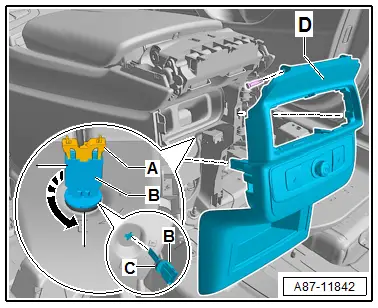
Installing
Install in reverse order of removal. Note the following:
- Check the seal -C- for damage and proper seating.
- Perform the basic setting and the output diagnostic test mode (for functionality check) of the A/C system. Refer to Vehicle Diagnostic Tester in the "Guided Fault Finding" function.
- Check the DTC memory on the Front A/C Display Control Head -E87- and erase any displayed malfunctions. Refer to Vehicle Diagnostic Tester in the "Guided Fault Finding" function.
Rear Upper Body Vent Temperature Sensor -G537-, Removing and Installing, "Mid" or "Mix" A/C System
 Note
Note
- The Rear Upper Body Vent Temperature Sensor -G537- is only installed on vehicles with a "Mid" or "Mix" A/C system in the rear air distribution housing.
- After installing a new actuator, check the activation via the Front A/C Display Control Head -E87- and the actuator function. Refer to Vehicle Diagnostic Tester in the "Guided Fault Finding" function.
Removing
- Turn off the ignition.
- Remove the rear air distribution housing. Refer to → Chapter "Heater and A/C Unit, Removing and Installing, Mid or Mix A/C System".
- Remove the connector -A-.
- Turn the sensor -B- 90º in direction of -arrow- and remove it.
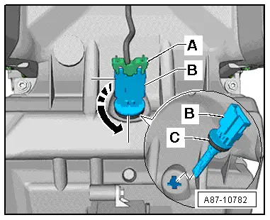
Installing
Install in reverse order of removal. Note the following:
- Check the seal -C- for damage and proper seating.
- Perform the basic setting and the output diagnostic test mode (for functionality check) of the A/C system. Refer to Vehicle Diagnostic Tester in the "Guided Fault Finding" function.
- Check the DTC memory on the Front A/C Display Control Head -E87- and erase any displayed malfunctions. Refer to Vehicle Diagnostic Tester in the "Guided Fault Finding" function.
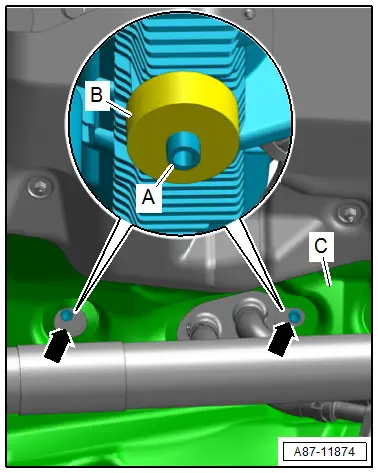
Condensation Water Drain Hose, Checking
Checking
- Check if the insulation -C- is secured correctly and that the condensation water drain is seated in the opening.
- Clean condensation water drain -arrows- from below, for example with a piece of wire (with the vehicle lifted and the heat shield installed).
- The condensation water drains must not be sticky with wax or underbody sealant.
 Note
Note
- There is no valve in the two condensation water drains.
- The condensation water drain are sealed with a foam seal -B- from the inside against the floor panel of the center console.
- For the condensation water to drain out of the vehicle, condensation water drains -A- must protrude slightly from the floor panel of center console.