Audi Q7: Rear Fresh Air Blower -V80-, Removing and Installing
Rear Fresh Air Blower -V80-, Removing and Installing, "Mid" or "Mix" A/C System
 Caution
Do not grasp fan wheel of Rear Fresh Air Blower -V80-, force against the fan wheel or shifting the balancing weights fastened to fan wheel may cause imbalance and then problems during operation.
Removing
- Remove the rear air distribution housing. Refer to → Chapter "Heater and A/C Unit, Removing and Installing, Mid or Mix A/C System".
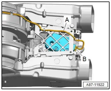
- Remove the bolts -B-.
- Pry up the air duct -A- in the area of the rear fresh air blower -C- and remove in the direction of -arrow-.
- Remove the adjustment motors, operating lever, and rear upper body vent temperature sensor on the air distribution housing. Refer to → Chapter "Overview - Rear Adjustment Motor".
- Free up the wiring harness.

Installing
Install in reverse order of removal.
Tightening Specifications
- Refer to → Chapter "Overview - Heater and A/C Unit Attachments and Air Intake Housing, Heater Core, Mid or Mix A/C System"
Rear Fresh Air Blower -V80-, Removing and Installing, "High" A/C System
Removing
- Remove the heater and A/C unit. Refer to → Chapter "Heater and A/C Unit, Removing and Installing, High A/C System".
- Disconnect the connector -B- and free up the wiring harness -A-.
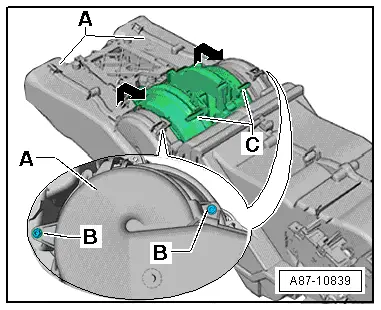
- Remove the bolts -B-.
- Pry up the air duct -A- in the area of the rear fresh air blower -C- and remove in the direction of -arrow-.
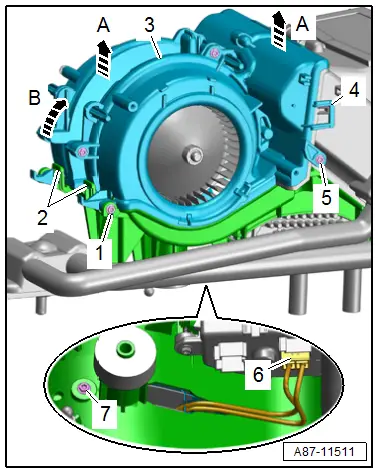
- Disconnect the connector -6-.
- Remove the bolts -1, 5 and 7-.
- Release the catches -2- and lift up the fresh air blower -3- slightly from the housing -A arrows-.
- Release the catch -3- and pivot the fresh air blower in the direction of -arrow A-.
- Remove the fresh air blower at the same time guide out the wiring harness through the opening in the housing.
Installing
Install in reverse order of removal. Note the following:
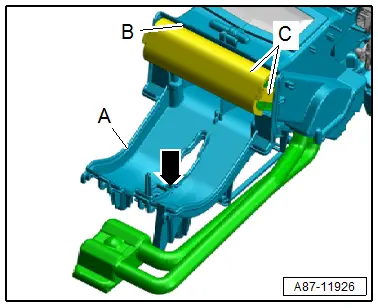
- Check the evaporator for debris and the corresponding seals -B- for correct bonding and damage.
- Check the condensation water drain -arrow- for debris.
 Note
Note
- If the Rear Fresh Air Blower -V80- and the evaporator are replaced at the same time, first install the Rear Fresh Air Blower -V80- and then the new evaporator. The foam seal on new evaporator -B- is not preformed und must first be pressed together. This is not so simple via the Rear Fresh Air Blower -V80-.
- Pressure marks on the foam seal on evaporator -B- from the Rear Fresh Air Blower -V80- are not damage. They facilitate assembly.
- Check the connection points -A and B- (groove/spring connection) for damage.
- Damaged or improperly joined components can result in noises during operation of the A/C system.
Tightening Specifications
- Refer to → Chapter "Overview - Heater and A/C Unit Attachments and Air Intake Housing, Heater Core, High A/C System Section 1"
- Perform the basic setting and the output diagnostic test mode of the A/C system. Refer to Vehicle Diagnostic Tester in the "Guided Fault Finding" function.
 Note
Note
- In this vehicle, the control motors are equipped with electronics. During the basic setting, a new control motor learns its position on the heater and A/C unit and can then be activated by the Rear A/C Display Control Head -E265- (currently all control motors are identical). Refer to Vehicle Diagnostic Tester in the "Guided Fault Finding" function.
- During the basic setting, the actuators are assigned and adapted corresponding to the switching sequence of the wiring. If this sequence does not conform with the specification, the actuators will adapt incorrectly and the door control will be wrong. Refer to → Chapter "Main Wiring Diagram for A/C System Actuators".
- Check the DTC memory on the Rear A/C Display Control Head -E265- and the Front A/C Display Control Head -E87-) and erase any malfunctions shown. Refer to Vehicle Diagnostic Tester in the "Guided Fault Finding" function.
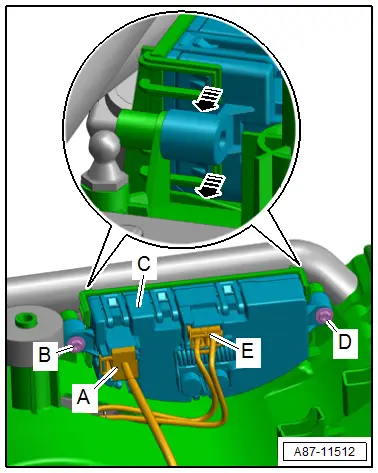
Fresh Air Blower Control Module, Removing and Installing
 WARNING
The heat sink on the Rear Fresh Air Blower Control Module -J391- may be hot.
Removing
- Remove the heater and A/C unit. Refer to → Chapter "Heater and A/C Unit, Removing and Installing, High A/C System".
- Disconnect the connectors -A and E-.
- Remove the bolts -B and D-.
- Release the catches in direction of -arrows- and remove the control module -C-.
Installing
Install in reverse order of removal. Note the following:
 Note
Note
There are different versions of the fresh air blower control module. Allocation. Refer to the Parts Catalog.
Tightening Specifications
- Refer to → Chapter "Overview - Attachments for Heater and A/C Unit and Air Intake Housing"
- Perform the basic setting and the output diagnostic test mode of the A/C system. Refer to Vehicle Diagnostic Tester in the "Guided Fault Finding" function.
- Check the event memory of the Rear A/C Display Control Head -E265- (and the Front A/C Display Control Head -E87-) and erase any displayed malfunctions. Refer to Vehicle Diagnostic Tester in the "Guided Fault Finding" function if necessary.
Heater Core, Removing and Installing
Removing
- Remove the heater and A/C unit. Refer to → Chapter "Heater and A/C Unit, Removing and Installing, High A/C System".
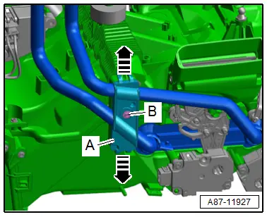
- Remove the bolt in direction of -B-.
- Release the catches in direction of -arrows- and remove the bracket -A-.
- Remove the right rear temperature control door motor. Refer to → Chapter "Right Rear Temperature Control Door Motor -V314-, Removing and Installing".
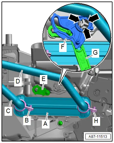
- Release the catches -arrows- on the support bracket, and remove the curved washer -G- and the relay lever -F-.
- Turn back the lever -E- from the heat exchanger.
- Remove the heat exchanger from the heater and A/C unit.
- Remove the coolant pipes -C and D- to do so loosen the screw-type clamps -B and H-.
Installing
Install in reverse order of removal. Note the following:
- Check the heater and A/C unit via the installation slot for contamination and clean if necessary.
- Check the seals -E- on the heater core; only install a heater core with seals that are not damaged and are secured glued on.
 Note
Note
If seal is damaged or is not properly installed, cold air can flow past the heater core which can result in complaints due to cold air from the heater and A/C unit or noises.
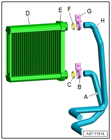
- Lightly moisten the connections of the heat exchanger -D- with coolant or grease with silicone grease or example Silicone Grease -G 000 405 A2-.
- Check the connection area of the coolant pipes -A and H- for damage or contamination.
 Note
Note
Even slight damage (a scratch) or a little bit of dirt (a hair) can cause leakage at a connection.
- Lightly moisten the seals -C and F- with coolant (or lightly with silicone grease).
- Place the new screw-type clamps -B and G- on the coolant pipes -A and H-.
- Insert the coolant pipes in the connections of the heat exchanger and push in all the way.
- Insert the heater core -A- all the way into installation shaft -D- of the heater and A/C unit.
- Align the coolant pipes on the heater and A/C unit and tighten the screw-type clamps.
- Add coolant and check the heat exchanger for leaks. Refer to → Rep. Gr.19; Coolant System/Coolant; Coolant, Draining and Filling.
- Perform the basic setting and the output diagnostic test mode (for functionality check) of the heating and A/C system. Refer to Vehicle Diagnostic Tester in the "Guided Fault Finding" function.
 Note
Note
- In this vehicle, the actuators are equipped with electronics. During the basic setting, a new control motor learns its position on the heater and A/C unit and can then be activated by the Front A/C Display Control Head -E87- (currently all actuators are identical). Refer to Vehicle Diagnostic Tester in the "Guided Fault Finding" function.
- During the basic setting, the actuators are assigned and adapted corresponding to the switching sequence of the wiring. If this sequence does not conform with the specification, the actuators will adapt incorrectly and the door control will be wrong. Refer to → Chapter "Main Wiring Diagram for A/C System Actuators".
- Check the DTC memory on the Front A/C Display Control Head -E87- and erase any displayed malfunctions. Refer to Vehicle Diagnostic Tester in the "Guided Fault Finding" function.

