Audi Q7: Heating Output and Temperature Control Door Activation, Checking
 Note
Note
- Depending on vehicle equipment, there are different versions of the A/C system for the Audi Q7. Make sure to use the correct version and pay attention to the allocation of different components. Refer to → Chapter "A/C System Versions" and Parts Catalog.
- For vehicles with a "Low" A/C system, there is no air distribution housing and no rear heater and A/C unit installed.
- For vehicles with a "Mid" or "Mix" A/C system, a rear air distribution housing is installed (but no rear heater and A/C unit).
- For vehicles with a "High" A/C system, a rear heater and A/C unit is installed.
- Close the engine hood.
- Close the doors, the engine hood, the windows, the sliding sunroof and the rear lid.
- Open all instrument panel vents and the vents in the rear center console.
- Open the vents in the left and right B-pillars.
- Close the vent for glove compartment cooling (in the glove compartment).
- Turn on the ignition and activate the ready mode. The engine starts automatically as needed (on vehicles with a Start/Stop System).
- Start the engine.
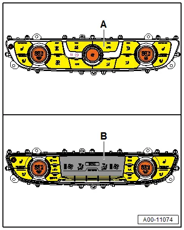
Set the following on the Front A/C Display Control Head -E87-:
 Note
Note
By selecting the "SYNC" function on the Front A/C Display Control Head -E87- (only on version -B-), the settings on the front driver side are applied to the front passenger side and also to the Rear A/C Display Control Head -E265-.
- Select the SYNC function on the Front A/C Display Control Head -E87-.
- Select "Auto" mode for the driver side (and the front passenger side) (the indicator lamp in the AUTO button(s) illuminate).
- Temperature on the driver and front passenger side set to "cold" ("LO" in the Front A/C Display Control Head -E87- and MMI display).
- The A/C compressor is on (the indicator lamp in the A/C MAX button comes on).
- Fresh air blower (front and rear) set to "maximum speed" (shown in the Front A/C Display Control Head -E87- and MMI display).
- Set the airflow direction on the driver and front passenger side to "footwell" and "instrument panel vent" using the knob or buttons on the Front A/C Display Control Head -E87- (shown in the display or the buttons for the Front A/C Display Control Head -E87-).
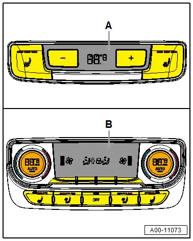
For a "Mid" or "Mix" A/C system, the following is set on the Rear A/C Display Control Head -E265-:
- "Cold" temperature setting ("LO").
 Note
Note
- Depending on vehicle equipment, there are different versions of the A/C system for the Audi Q7. Make sure to use the correct version and pay attention to the allocation of different components. Refer to → Chapter "A/C System Versions" and Parts Catalog.
- For vehicles with a "Mid" or "Mix" A/C system, the air temperature and amount of air that is calculated and regulated by the Front A/C Display Control Head -E87- are also influenced by the setting on the Rear A/C Display Control Head -E265-. However, only the temperature can be adjusted on this Rear A/C Display Control Head -E265-. Refer to → Chapter "Rear A/C Display Control Head -E265-, Removing and Installing, High A/C System".
For a "High" A/C system, the following is set on the Rear A/C Display Control Head -E265-:
- "Auto" mode (the indicator lamps in one or both AUTO buttons illuminate).
- Temperature preselection "cold" (display "LO" for the left and right sides).
- Preselection for the Rear Fresh Air Blower -V80-"maximum speed".
- Set the air flow direction via the dials on the Rear A/C Display Control Head -E265- for the left and right side to "footwell" and "B-pillar vents" (shown in the display of the Rear A/C Display Control Head -E265-).
 Note
Note
- The indicator lamps in the AUTO -buttons turn off when performing manual changes for the airflow direction and/or the fresh air blower speed.
- The maximum possible fresh air blower speed depends on several conditions (coolant temperature, vehicle voltage, etc.)
- The instrument panel vents, the B-pillar vents, and the vents in the rear center console are open.
- Initiate Guided Fault Finding for the front A/C system and select the "Read measured values" function. Refer to Vehicle Diagnostic Tester.
- Let the A/C system run a few minutes at maximum cooling output (A/C compressor is switched on, indicator lamp in the A/C MAX button comes on).
- Compare the measured value for the Evaporator Vent Temperature Sensor -G263- with the measured values from the Left Front Upper Body Vent Temperature Sensor -G385-, the Right Front Upper Body Vent Temperature Sensor -G386-, the Left Footwell Vent Temperature Sensor -G261-, the Right Footwell Vent Temperature Sensor -G262- (and the Rear Upper Body Vent Temperature Sensor -G537-, which is only on a "Low", "Mid" or "Mix" A/C system).
 Note
Note
- Depending on vehicle equipment, there are different versions of the A/C system for the Audi Q7. Make sure to use the correct version and pay attention to the allocation of different components. Refer to → Chapter "A/C System Versions" and Parts Catalog.
- The Rear Upper Body Vent Temperature Sensor -G537- is only installed on vehicles without a rear heater and A/C unit (with a "Low", "Mid" or "Mix" A/C system, with or without a Rear A/C Display Control Head -E265- version -A-).
Specified Values
- After five minutes, the temperature sensor measured values (downstream of the heater core) for the Left Front Upper Body Vent Temperature Sensor -G385-, Right Front Upper Body Vent Temperature Sensor -G386-, Left Footwell Vent Temperature Sensor -G261-, Right Footwell Vent Temperature Sensor -G262- (and the Rear Upper Body Vent Temperature Sensor -G537-) may be greater than the value for the Evaporator Vent Temperature Sensor -G263- by a maximum of 10 ºC (50 ºF).
 Note
Note
Due to the design of the heater and A/C unit and the air routing in the vehicle, there is always a certain increase in air temperature.
If the required values are not reached, perform a fault finding at a temperature increase on the evaporator.
 Note
Note
- If the measured value in one or two temperature sensors deviates from the measured values of the other temperature sensors, check this temperature sensor and the control motor which activates the temperature control door upstream from this temperature sensor. Refer to Vehicle Diagnostic Tester in the "Guided Fault Finding" function.
- Depending on vehicle equipment, there are different versions of the A/C system for the Audi Q7. Make sure to use the correct version and pay attention to the allocation of different components. Refer to → Chapter "A/C System Versions" and Parts Catalog.

Then additionally in vehicles with a "High" A/C system (with a rear heater and A/C unit and a Rear A/C Display Control Head -E265- version -B-).
- Initiate Guided Fault Finding of the rear A/C system and select the "read measured values" function. Refer to Vehicle Diagnostic Tester in the "Guided Fault Finding" function.
- Compare the measured value of the Evaporator Vent Temperature Sensor -G263- with the measured value of the Left Rear Upper Body Vent Temperature Sensor -G635-, the Right Rear Upper Body Vent Temperature Sensor -G636-, the Left Rear Footwell Vent Temperature Sensor -G637- and the Right Rear Footwell Vent Temperature Sensor -G638-.
Specified Values
- The displayed measured values may be a maximum of 10 ºC (50 ºF) greater than the displayed measured value of the Evaporator Vent Temperature Sensor -G263-.
If the required values are not reached. Refer to → Chapter "Malfunction Determination if Cooling Output of Front A/C System is OK but Required Values not Achieved in Rear".
Continuation for All Vehicles
- Set the temperature on the driver and front passenger side to "warm" using the knobs on the Front A/C Display Control Head -E87- ("Hi" in the displays for the Head Front A/C Display Control -E87-).
- For a vehicle with a "Mid" or "Mix" A/C system, set the temperature to "warm" using the buttons on the Rear A/C Display Control Head -E265- ("Hi" in the display for the Rear A/C Display Control Head -E265-).
- For a vehicle with a "High" A/C system, set the temperature on the driver and front passenger side to "warm" using the buttons on the Rear A/C Display Control Head -E265- ("Hi" in the displays for the Rear A/C Display Control Head -E265-).
 Note
Note
- Depending on vehicle equipment, there are different versions of the A/C system for the Audi Q7. Make sure to use the correct version and pay attention to the allocation of different components. Refer to → Chapter "A/C System Versions" and Parts Catalog.
- For vehicles with a Front A/C Display Control Head -E87- version -B-, the settings on the front driver side are applied to the front passenger side and also to the Rear A/C Display Control Head -E265- by selecting the "SYNC" function.
The display for the preselected temperature changes for all vents (the driver and front passenger side, for the left and right rear) from "LO" to "HI".
- Check the measured values for the Left Front Upper Body Vent Temperature Sensor -G385-, Right Front Upper Body Vent Temperature Sensor -G386-, Left Footwell Vent Temperature Sensor -G261-, Right Footwell Vent Temperature Sensor -G262- (and Rear Upper Body Vent Temperature Sensor -G537-, only on a "Low", "Mid" or "Mix" A/C system) that are displayed in the "Read measured values" function of Guided Fault Finding for the Front A/C Display Control Head -E87-. Refer to Vehicle Diagnostic Tester in the "Guided Fault Finding" function.

 Note
Note
The Rear Upper Body Vent Temperature Sensor -G537- is only installed on vehicles with a "Low", "Mid" or "Mix" A/C system (with or without a rear air distribution housing, as well as with or without a Rear A/C Display Control Head -E265- version -A-.
Specified Values
- The measured temperature for all temperature sensors increases to above 50 ℃ (122 ºF) (depending on the engine temperature at the time).
 Note
Note
- For vehicles with a Start/Stop System, the Coolant Recirculation Pump -V50- maintains the coolant flow through the heater core for the heater in the heater and A/C unit when the engine is not running.
- The Coolant Recirculation Pump -V50- can be installed in different locations. In most vehicles, it is installed in the engine compartment (on a 6-cylinder TDI engine, for example, it is under the right fender).
- The activation of the Coolant Recirculation Pump -V50- varies. In most vehicles, it is activated by the respective Engine Control Module -J623- at the request of the Front A/C Display Control Head -E87-. Refer to Vehicle Diagnostic Tester in the "Guided Fault Finding" function and refer to → Wiring diagrams, Troubleshooting & Component locations.
The required values are achieved at all temperature sensors:
- Continuation of testing for vehicles with a "Low", "Mid" or "Mix" A/C system (without a rear heater and A/C unit, with or without a Rear A/C Display Control Head -E265- version -A-).
- Continuation of testing for vehicles with a "High" A/C system (with a rear heater and A/C unit and a Rear A/C Display Control Head -E265- version -B-).
 Note
Note
- For vehicles with a "Low" A/C system, there is no Rear A/C Display Control Head -E265-, no air distribution housing and no rear heater and A/C unit installed.
- For vehicles with a "Mid" or "Mix" A/C system, a Rear A/C Display Control Head -E265- version -A- and a rear air distribution housing is installed (but no rear heater and A/C unit). Refer to → Chapter "Rear A/C Display Control Head -E265-, Removing and Installing, High A/C System".
- For vehicles with a "High" A/C system, a Rear A/C Display Control Head -E265- version -B- and a rear heater and A/C unit are installed. Refer to → Chapter "Rear A/C Display Control Head -E265-, Removing and Installing, High A/C System".
- If the required values are not reached on any of the temperature sensors:
- Check the activation and function of the Coolant Pump -V50- (of the Recirculation Pump -V55-) and of the Coolant Shut-Off Valve -N82- (of the Heater Coolant Shut-Off Valve -N279-). Refer to Vehicle Diagnostic Tester in the "Guided Fault Finding" function.
- Check the incorporation of the A/C system into the coolant circuit. Refer to → Chapter "Incorporating the Heating and A/C System in the Coolant Circuit".
- Check the coolant circuit bleeding. Refer to → Rep. Gr.19; Coolant System/Coolant; Coolant, Draining and Filling
- Check the heating output of the A/C system at an engine speed of approximately 1500 to 2000 RPM (repeat the test at a higher engine speed). If the required heating output is reached at this engine speed, the malfunction is not in the heater and A/C unit, but rather in the coolant circuit (incorporation of the A/C system into the coolant circuit, engine coolant pump delivery rate, the coolant flowing through heater core in the front heater and A/C unit, incorporation of the Coolant Recirculation Pump -V50- into the coolant circuit, etc.). Refer to → Chapter "Incorporating the Heating and A/C System in the Coolant Circuit" and → Rep. Gr.19; Coolant System/Coolant; Connection Diagram - Coolant Hoses.
- Check that the engine coolant pump is functioning correctly (if a coolant pump is faulty or a Coolant Recirculation Pump -V50- is incorporated incorrectly, there may not be enough coolant flowing through the heater core for the heater in the front and rear heater and A/C unit). Refer to → Rep. Gr.19; Coolant Pump/Coolant Thermostat; Overview - Electric Coolant Pump.
 Note
Note
For vehicles with an engine with a regulated coolant circuit (for example, with a regulated coolant pump and a Cylinder Head Coolant Valve -N489-), there is currently no Coolant Shut-Off Valve -N82- installed. On an engine with a regulated coolant pump, the engine control module activates the coolant pump, and in doing so regulates the coolant circulation.
If the required values are not reached at only one or two temperature sensors:
- Check the activation and function of the various actuators for the temperature control doors in the front heater and A/C unit. Refer to Vehicle Diagnostic Tester in the "Guided Fault Finding" function.
- Check the measured values of the various temperature sensors. Refer to Vehicle Diagnostic Tester in the "Guided Fault Finding" function.
- Perform fault finding in the case of an increase in temperature after the evaporator.
- Check the foam seal on the heat core for the heater for the front heater and A/C unit.
- On vehicles with an Auxiliary Heater Control Module -J604- (and an Auxiliary Heater Heating Element -Z35-) check the separation between the left and the right side in the front heater and A/C unit via the installation slot for the Auxiliary Heater Heating Element -Z35-. Refer to → Chapter "Auxiliary Heater Control Module -J604- (with Auxiliary Heater Heating Element -Z35-) Checking, Removing and Installing".
- Check the coolant circuit bleeding. Refer to → Rep. Gr.19; Coolant System/Coolant; Coolant, Draining and Filling
Additional check for vehicles with a "High" A/C system (with a rear heater and A/C unit) check the heating output of the rear heater and A/C unit.
 Note
Note
- Continuation of the heat output test and the activation of the temperature control doors on a vehicle with a rear heater and A/C unit (with a "High" A/C system).
- Depending on vehicle equipment, there are different versions of the A/C system for the Audi Q7. Make sure to use the correct version and pay attention to the allocation of different components. Refer to → Chapter "A/C System Versions" and Parts Catalog.
The heating output and activation of the temperature doors of the front A/C system were tested and are OK. Refer to → Chapter "Heat Output and Temperature Door Activation, Checking"
- Read the "measured values" of the Rear A/C Display Control Head -E265- the displayed measured values for the various temperature sensors: left vent temperature sensor -G635-, -G636-, -G637- and -G638-. Refer to Vehicle Diagnostic Tester in the function "Guided Fault Finding".
 Note
Note
A commercially available thermometer can also be used to measure the temperature of the air coming out of the vents in the rear center console (left and right).
Specified Values
- The measured temperature for all temperature sensors increases to above 50 ℃ (122 ºF) (depending on the engine temperature at the time).
The required values are achieved at all temperature sensors:
- Continuation of the test.
If the required values are not reached on any of the temperature sensors:
- Check the activation and function of the Coolant Pump -V50- (of the Recirculation Pump -V55-) and of the Coolant Shut-Off Valve -N82- (of the Heater Coolant Shut-Off Valve -N279-). Refer to Vehicle Diagnostic Tester in the "Guided Fault Finding" function.
- Check the incorporation of the rear A/C system into the coolant circuit. Refer to → Chapter "Incorporating the Heating and A/C System in the Coolant Circuit".
- Check the coolant circuit bleeding. Refer to → Rep. Gr.19; Coolant System/Coolant; Coolant, Draining and Filling
- Check the heating output at an engine speed of approximately 1500 to 2000 RPM (repeat the test at a higher engine speed). If the required heating output is not reached at this engine speed, the malfunction is not in the heater and A/C unit but rather in the coolant circuit (check the incorporation of the A/C system in the coolant circuit, engine coolant pump delivery, the coolant flowing through the heater core in the rear heater and A/C unit, etc.). Refer to → Chapter "Incorporating the Heating and A/C System in the Coolant Circuit" and → Rep. Gr.19; Coolant System/Coolant; Connection Diagram - Coolant Hoses.
- Check the regulator for the coolant temperature in the engine (the engine coolant may not heat properly if the regulator is malfunctioning). Refer to → Rep. Gr.19; Coolant Pump/Coolant Regulation; Coolant Regulator, Checking .
- Check that the engine coolant pump is functioning correctly (if a coolant pump is faulty or a Coolant Recirculation Pump -V50- is incorporated incorrectly, there may not be enough coolant flowing through the heater core for the heater in the front and rear heater and A/C unit). Refer to → Rep. Gr.19; Coolant Pump/Coolant Regulation; Overview - Coolant Pump.
- Check the foam seal on the heat core for the heater for the rear heater and A/C unit. Refer to → Chapter "Heater Core, Removing and Installing".
If the required values are not reached at only one or two temperature sensors:
- Check the activation and function of the various actuators for the temperature control doors in the rear heater and A/C unit. Refer to Vehicle Diagnostic Tester in the "Guided Fault Finding" function.
- Check the measured values of the various temperature sensors in the rear air ducts. Refer to Vehicle Diagnostic Tester in the "Guided Fault Finding" function.
Continuation of the heating output test of the front heater and A/C units (check the separation for the temperature control between the left and right side in the heater and A/C unit).
 Note
Note
Depending on vehicle equipment, there are different versions of the A/C system for the Audi Q7. Make sure to use the correct version and pay attention to the allocation of different components. Refer to → Chapter "A/C System Versions" and Parts Catalog.
- Using the knob on the Front A/C Display Control Head -E87- adjust the temperature setting for the front passenger side to "cold" ("LO" is displayed) in the display of the Front A/C Display Control Head -E87- for the front passenger side.

- On vehicles with a "High" A/C system using the knob on the Rear A/C Display Control Head -E265- (version -B-) adjust the temperature setting for the passenger side rear to "cold" ("LO" is displayed) in the display of the Rear A/C Display Control Head -E265- for the rear passenger side.
- The temperature setting for the driver side (front and rear) remains on "warm" ("HI" is displayed) in the display of the Front A/C Display Control Head -E87- (on a "Mix" or "High" A/C system and the Rear A/C Display Control Head -E265- on a "Mid", "Mix" or "High" A/C system).
 Note
Note
- On a vehicle with a "Mid" or "Mix" A/C system the temperature setting for the (front) driver side remains on "warm" ("HI" is displayed) in the display of the Front A/C Display Control Head -E87-. The adjustment on the Rear A/C Display Control Head -E265- for the rear remains on "warm" ("HI" is displayed in the display).
- On a vehicle with a "High" A/C system the temperature setting for the driver side (front and rear) remains on "warm" ("HI" is displayed) in the display of the Front A/C Display Control Head -E87- and the Rear A/C Display Control Head -E265-.
- Initiate Guided Fault Finding of the front A/C system and select the "read measured values" function. Refer to Vehicle Diagnostic Tester in the "Guided Fault Finding" function.
- Let the A/C system run for a few minutes with this setting (the A/C compressor is switched on, the indicator lamp in the A/C MAX button illuminates).
- Compare the measured value for the Evaporator Vent Temperature Sensor -G263- with the measured values from the Left Front Upper Body Vent Temperature Sensor -G385-, the Right Front Upper Body Vent Temperature Sensor -G386-, the Left Footwell Vent Temperature Sensor -G261-, the Right Footwell Vent Temperature Sensor -G262- (and the Rear Upper Body Vent Temperature Sensor -G537-, which is only on a "Low", "Mid" or "Mix" A/C system).

 Note
Note
- The Rear Upper Body Vent Temperature Sensor -G537- is only installed on vehicles with a "Low", "Mid" or "Mix" A/C system with or without a rear air distribution housing, (with or without a Rear A/C Display Control Head -E265- version -A-).
- At the temperature setting "warm" for one side (the driver or front passenger side), the target outflow temperature at the evaporator in the front heater and A/C unit is regulated by the Climatronic Control Module -J255- to a higher value (up to approximately 10 ºC (50 ºF) ).
- On a vehicle with a "Low" A/C system (without a Rear A/C Display Control Head -E265-, without an air distribution housing and a rear heater and A/C unit) the temperature of the air which flows from the front heater and A/C unit to the rear vent is regulated from the Front A/C Display Control Head -E87- so that the air out of the vent for the front area has an average temperature. The target temperature for the air from the vents in the front area is calculated via the setting for the left and right side on the Front A/C Display Control Head -E87- from the Front A/C Display Control Head -E87-. However, if a setting which no longer regulates the temperature (for example, "HI" for maximum heating or "LO" for maximum cooling) is present on the Front A/C Display Control Head -E87-, the temperature of the air from the vents in the front area is no longer regulated. If, for example, maximum heating "HI" is set on the Front A/C Display Control Head -E87- for one side and maximum cooling "LO" for the other side, the air for the vents in the front area is maximally heated.

- On a vehicle with a "Mid" or "Mix" A/C system (with a version -A-Rear A/C Display Control Head -E265-, and an air distribution housing but without a rear heater and A/C unit) the temperature of the air which flows from the front heater and A/C unit to the rear air distribution housing is regulated from the Front A/C Display Control Head -E87- so that the air out of the vent for the front area has an average temperature. The target temperature for the air from the vents in the front area is calculated via the adjustment for the left and right side on the Front A/C Display Control Head -E87- and the adjustment Rear A/C Display Control Head -E265- from the Front A/C Display Control Head -E87-. However, if a setting which no longer regulates the temperature (for example, "HI" for maximum heating or "LO" for maximum cooling) is present on the Front A/C Display Control Head -E87-, the temperature of the air from the vents in the front area is no longer regulated. If, for example, maximum heating "HI" is set on the Front A/C Display Control Head -E87- for one side and maximum cooling "LO" for the other side depending on the adjustment on the Rear A/C Display Control Head -E265- the air for the vents in the front area is maximally heated or cooled.
Specified values on a vehicle with a "Low"Mid" or "Mix" A/C system:
- A temperature which corresponds approximately to the temperature on the warmer side is set on the Rear Upper Body Vent Temperature Sensor -G537- (ignore the measured value).
Specified values on a vehicle with a "High" A/C system:
- On the Left Front Upper Body Vent Temperature Sensor -G385- and Left Footwell Vent Temperature Sensor -G261-, the temperature remains above 50 ºC (122 ºF) (depending on the current engine temperature).
- On the Right Front Upper Body Vent Temperature Sensor -G386- and Right Footwell Vent Temperature Sensor -G262-, the temperature drops to a value which may be a maximum of 15 ºC (59 ºF) higher than the measured value of the Evaporator Vent Temperature Sensor -G263- within 5 minutes.
- The temperatures of the temperature sensors on one side (Left Front Upper Body Vent Temperature Sensor -G385- and Left Footwell Vent Temperature Sensor -G261-) and ( Right Front Upper Body Vent Temperature Sensor -G386- and Right Footwell Vent Temperature Sensor -G262-) displayed in the "read measured values" function of the Guided Fault Finding equalize within 5 minutes (the particular temperature difference is less than 9 ºC (48.2 ºF) ).
 Note
Note
- For vehicles with a Start/Stop System, the Coolant Recirculation Pump -V50- maintains the coolant flow through the heater core for the heater in the heater and A/C unit when the engine is not running.
- The Coolant Recirculation Pump -V50- can be installed in different locations. In most vehicles, it is installed in the engine compartment (on a 6-cylinder TDI engine, for example, it is under the right fender). Refer to → Chapter "Incorporating the Heating and A/C System in the Coolant Circuit".
- The activation of the Coolant Recirculation Pump -V50- varies. In most vehicles, it is activated by the respective Engine Control Module -J623- at the request of the Front A/C Display Control Head -E87-. Refer to Vehicle Diagnostic Tester in the "Guided Fault Finding" function and refer to → Wiring diagrams, Troubleshooting & Component locations.

- On a vehicle with a "Low"Mid" or "Mix" A/C system (without a rear heater and A/C unit) with and without a rear air distribution housing and Rear A/C Display Control Head -E265- (version -A-) adjust the temperature setting for the front passenger side to 18 ºC (64.4 ºF) and for the driver side to 28 ºC (82.4 ºF).
- A temperature between the values for the left and right is set on the Rear Upper Body Vent Temperature Sensor -G537- (the air for the left and right side from the front heater and A/C unit mixes in the rear air distribution housing).
- On vehicles with a "High" A/C system initiate the Guided Fault Finding of the rear A/C system (with a rear heater and A/C unit and a Rear A/C Display Control Head -E265- (version -B-) select the function "Read measured values". Refer to Vehicle Diagnostic Tester.
- Compare the measured value of the Evaporator Vent Temperature Sensor -G263- to the measured values of the Left Rear Upper Body Vent Temperature Sensor -G635-, the Right Rear Upper Body Vent Temperature Sensor -G636-, the Left Rear Footwell Vent Temperature Sensor -G637- and the Right Rear Footwell Vent Temperature Sensor -G638-.

Specified values on a vehicle with a "High" A/C system:
- The temperature on the Left Rear Upper Body Vent Temperature Sensor -G635- and Left Rear Footwell Vent Temperature Sensor -G637- remains higher than 50 ºC (122 ºF) (depending on the current engine temperature).
- On the Right Rear Upper Body Vent Temperature Sensor -G636- and Right Rear Footwell Vent Temperature Sensor -G638-, the temperature drops to a value which is a maximum of 15 ºC (59 ºF) higher than the measured value of the Evaporator Vent Temperature Sensor -G263- within five minutes.
- The temperatures of the temperature sensors on one side (-G635- and -G637-) and (-G636-, -G638- and -G262-) ) displayed in the "read measured values" function of the Guided Fault Finding equalize within five minutes (the particular temperature difference is less than 9 ºC (48.2 ºF) ).
If the target values are reached, the test is complete.
 Note
Note
If the temperature for the driver side is set to "LO" and the temperature for the front passenger side is set to "HI", this test can be performed again using opposite measured values.
If the specified values are not reached, check the following:
- Check the activation and functionality of the various adjustment motors for the temperature doors in the front or rear heater and A/C unit (depending on where the target values were not reached). Refer to Vehicle Diagnostic Tester in the "Guided Fault Finding" function.
- Check the foam seal on the heat core for the heater of the front or rear heater and A/C unit (depending on where the target values were not reached). Refer to → Chapter "Heater Core, Removing and Installing" and → Chapter "Heater Core, Removing and Installing".
- Check the coolant circuit bleeding. Refer to → Rep. Gr.19; Coolant System/Coolant; Coolant, Draining and Filling.
- In vehicles with an Auxiliary Heater Heating Element -Z35-, check the separation between the left and right side in the front heater and A/C unit via the installation shaft for the Auxiliary Heater Heating Element -Z35- (only if the values are not reached in the front heater and A/C unit). Refer to → Chapter "Auxiliary Heater Control Module -J604- (with Auxiliary Heater Heating Element -Z35-) Checking, Removing and Installing".
- Check the activation and function of the Coolant Pump -V50- (of the Recirculation Pump -V55-) and of the Coolant Shut-Off Valve -N82- (of the Heater Coolant Shut-Off Valve -N279-). Refer to Vehicle Diagnostic Tester in the "Guided Fault Finding" function.
- Check that the engine coolant pump is functioning correctly (if a coolant pump is faulty or a Coolant Recirculation Pump -V50- is incorporated incorrectly, there may not be enough coolant flowing through the heater core for the heater in the front and rear heater and A/C unit). Refer to → Rep. Gr.19; Coolant System/Coolant; Connection Diagram - Coolant Hoses.
- Check the incorporation of the A/C system into the coolant circuit. Refer to → Chapter "Incorporating the Heating and A/C System in the Coolant Circuit".
Fault finding in the case of a temperature increase downstream from the evaporator (in the front heater and A/C unit)
 Note
Note
Depending on vehicle equipment, there are different versions of the A/C system for the Audi Q7. Make sure to use the correct version and pay attention to the allocation of different components. Refer to → Chapter "A/C System Versions" and Parts Catalog.
- Clamp off both coolant hoses to the front heater and A/C unit heater core, for example using Hose Clamps - Up To 40mm -3093-.
- Repeat the test for heating output and temperature door activation.
- Compare the measured value of the Evaporator Vent Temperature Sensor -G263- with the measured value of the Left Rear Upper Body Vent Temperature Sensor -G635-, the Right Rear Upper Body Vent Temperature Sensor -G636-, the Left Rear Footwell Vent Temperature Sensor -G637- and the Right Rear Footwell Vent Temperature Sensor -G638- (as well as the Rear Upper Body Vent Temperature Sensor -G537- on a "Low""Mid" or "Mix" A/C system).
- Do the measured values of the temperature sensors match when the coolant hoses are clamped off, and are the required values reached?

- Remove Hose Clamps - Up To 40mm -3093- from both coolant hoses.

- Check the activation and function of the Left Temperature Control Door Motor -V158-, the Right Temperature Control Door Motor -V159-, and the Rear Temperature Control Door Motor -V137- and the activation of each temperature door.

- Check the sensor with the deviating measured value for correct installation and check its electrical connections for contact resistance. Refer to Vehicle Diagnostic Tester in the "Guided Fault Finding" Function and → Wiring diagrams, Troubleshooting & Component locations.
- Correct the cause for the incorrect measured value, and if necessary, replace the defective sensor.
- Are the temperature flap activation and functionality OK?

- Check the function of the temperature door that increases the temperature.
- Repeat the heat output test and temperature door activation.

- Correct the cause of the malfunction. Refer to Vehicle Diagnostic Tester in the "Guided Fault Finding" function and → Wiring diagrams, Troubleshooting & Component locations.
- Repeat the heat output test and temperature door activation.

