Audi Q7: Incorporating the Heating and A/C System in the Coolant Circuit
Notes for Incorporating the Heating and A/C System in the Coolant Circuit
 Note
Note
- In vehicles with a diesel engine with and without a "parking heater", an Auxiliary Heater Control Module -J604- and an Auxiliary Heater Heating Element -Z35- are installed. Refer to → Chapter "Auxiliary Heater, Testing", → Chapter "Electrical Auxiliary Heater, Testing" and Audi Sales Program.
- On vehicles with a diesel engine is a "parking heater" is installed as optional equipment is activated as an auxiliary heater. Refer to the Audi Sales Program.
- On vehicles with a gasoline engine currently no Auxiliary Heater Heating Element - Z35- is installed as an auxiliary heater. The parking heater installed as optional equipment is activated as an auxiliary heater depending on the vehicle version.
- Mark the coolant hoses and coolant lines before removing, if the coolant hoses of the coolant lines are switched when installing, this can lead to problems with the ventilation of heat exchanger in the heater and A/C units and when operating the vehicle.
- Air in the coolant lines, the coolant hoses or in the heater and A/C units heater core can lead to noises in the coolant circuit. Refer to → Chapter "Coolant Circuit, Bleeding".
Incorporation of Front Heating and A/C System into Coolant Circuit, Vehicles without a Parking Heater
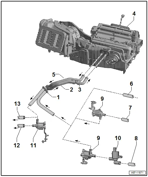
1 - Openings through the Lower Plenum Chamber Bulkhead for the Coolant Lines
2 - Coolant Hose, "supply"
- Inside the plenum chamber
3 - Bleeder Screw
- Refer to → Chapter "Coolant Circuit, Bleeding"
4 - Front Heater and A/C Unit
- Heat exchanger, removing and Installing with the heater and A/C unit installed. Refer to → Chapter "Heater Core, Removing and Installing".
- Heat exchanger, removing and Installing with the heater and A/C unit removed. Refer to → Chapter "Overview - Heater and A/C Unit".
5 - Coolant Hose, "Return"
- Inside the plenum chamber
6 - Coolant Supply from Engine
- For example on vehicles with a 6-cylinder TFSI engine
- Heating and A/C system integration into the engine coolant circuit. Refer to → Rep. Gr.19; Coolant System/Coolant; Connection Diagram - Coolant Hoses.
7 - Coolant Supply from Engine
- For example on vehicles with a 6-cylinder TDI engine
- Heating and A/C system integration into the engine coolant circuit. Refer to → Rep. Gr.19; Coolant System/Coolant; Connection Diagram - Coolant Hoses.
8 - Coolant Supply from Engine
- For example on vehicles with a 4-cylinder TFSI engine
- Heating and A/C system integration into the engine coolant circuit. Refer to → Rep. Gr.19; Coolant System/Coolant; Connection Diagram - Coolant Hoses.
9 - Coolant Recirculation Pump -V50-
- The Coolant Recirculation Pump -V50- is currently only installed in vehicles with certain engines in the coolant supply (for example, currently not installed on vehicles with a 4-cylinder TFSI or 6-cylinder TDI engine). Refer to → Rep. Gr.19; Coolant System/Coolant; Connection Diagram - Coolant Hoses).
- If a parking heater is installed as optional equipment in vehicles, a Coolant Recirculation Pump -V50- may not be installed. The Recirculation Pump - V55- installed on vehicles with a parking heater assumes this function. Refer to → Wiring diagrams, Troubleshooting & Component locations and the Vehicle Diagnostic Tester in the "Guided Fault Finding" function.
- Checking the Coolant Recirculation Pump -V50- functionality. Refer to → Chapter "Coolant Recirculation Pump -V50-, Function".
 Note
Note
- The Coolant Recirculation Pump -V50- supports the engine's own coolant pump to ensure sufficient and even coolant flow through the heat exchanger(s) of the A/C system.
- The Coolant Recirculation Pump -V50- can be installed in different locations. On most vehicles it is installed in the engine compartment (on the 6-cylinder TDI engine for example under the fender). Refer to → Rep. Gr.19; Coolant System/Coolant; Connection Diagram - Coolant Hoses.
- The activation of the Coolant Recirculation Pump -V50- varies. On most vehicles it is activated for example from the Engine Control Module -J623- at the request of the Front A/C Display Control Head -E87-. Refer to → Wiring diagrams, Troubleshooting & Component locations.
- Removing and installing. Refer to → Rep. Gr.19; Coolant Pump/Coolant Thermostat; Electric Coolant Pump, Removing and Installing.
10 - Coolant Shut-Off Valve -N82-
- The Coolant Shut-Off Valve -N82- is currently only installed in vehicles with certain engines (for example, currently not installed on vehicles with an 6-cylinder TFSI engine). Refer to → Rep. Gr.19; Coolant System/Coolant; Connection Diagram - Coolant Hoses).
- Check. Refer to Vehicle Diagnostic Tester in the "Guided Fault Finding" function
 Note
Note
- The Coolant Shut-Off Valve -N82- is open without activation. For the electrical function of the valve to be able to be checked, activation occurs at certain intervals (for example, brief activation lasting approximately one second at every twentieth engine start).
- The heater core can be shut off by the engine coolant circuit in various ways. Depending on the vehicle equipment, a Coolant Shut-Off Valve -N82- or Heater Coolant Shut-Off Valve -N279- can be installed. The Coolant Shut-Off Valve -N82- is for example activated by the Vehicle Electrical System Control Module -J519- upon request from the Engine Control Module -J623- or from the Front A/C Display Control Head - E87-. The Heater Coolant Shut-Off Valve -N279- is activated by the Auxiliary Heater Control Module -J364-. When switching on the ignition the activation takes place according to the request from the Engine Control Module -J623- or from the Front A/C Display Control Head -E87-. Refer to the Parts Catalog and the Vehicle Diagnostic Tester in the "Guided Fault Finding" function.
- The shutting off of the heater core by the engine coolant circuit also depends on the engine/transmission version (in certain versions shutoff is not performed while in other versions shutoff is performed in connection with the heating or cooling of the transmission oil). Refer to → Rep. Gr.19; Coolant System/Coolant; Connection Diagram - Coolant Hoses.
11 - Coolant Recirculation Pump -V50-
- The Coolant Recirculation Pump -V50- is currently only installed in vehicles with certain engines in the coolant return (for example, currently not installed on vehicles with an 6-cylinder TFSI engine). Refer to → Rep. Gr.19; Coolant System/Coolant; Connection Diagram - Coolant Hoses).
- Checking the Coolant Recirculation Pump -V50- functionality. Refer to → Chapter "Coolant Recirculation Pump -V50-, Function".
 Note
Note
- The Coolant Recirculation Pump -V50- supports the engine's own coolant pump to ensure sufficient and even coolant flow through the heat exchanger(s) of the heating and A/C system.
- The Coolant Recirculation Pump -V50- can be installed in different locations. On most vehicles it is installed in the engine compartment (on the 6-cylinder TDI engine for example under the fender). Refer to → Rep. Gr.19; Coolant System/Coolant; Connection Diagram - Coolant Hoses.
- The activation of the Coolant Recirculation Pump -V50- varies. On most vehicles it is activated for example from the Engine Control Module -J623- at the request of the Front A/C Display Control Head -E87-. Refer to → Wiring diagrams, Troubleshooting & Component locations.
- Removing and installing. Refer to → Rep. Gr.19; Coolant Pump/Coolant Thermostat; Electric Coolant Pump, Removing and Installing.
12 - Coolant Return to Engine
- Heating and A/C system integration into the engine coolant circuit. Refer to → Rep. Gr.19; Coolant System/Coolant; Connection Diagram - Coolant Hoses.
Incorporation of Front Heating and A/C System into Coolant Circuit, Vehicles with a Parking Heater
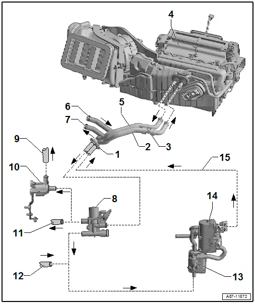
1 - Openings through the Lower Plenum Chamber Bulkhead for the Coolant Lines
2 - Coolant Hose, "Supply"
- Inside the plenum chamber
3 - Bleeder Screw
- Refer to → Chapter "Coolant Circuit, Bleeding"
4 - Front Heater and A/C Unit
- Heat exchanger, removing and Installing with the heater and A/C unit installed. Refer to → Chapter "Heater Core, Removing and Installing".
- Heat exchanger, removing and Installing with the heater and A/C unit removed. Refer to → Chapter "Overview - Heater and A/C Unit".
5 - Coolant Hose, "Return"
- Inside the plenum chamber
6 - Heater Core Connection in the Rear Heater and A/C Unit
- Return from the rear heater and A/C unit. Refer to → Chapter "Rear Heating and A/C system, Incorporation in the Coolant Circuit, High A/C System".
 Note
Note
The rear heater and A/C unit is optional equipment and only installed on vehicles with a "high" A/C system.
7 - Heater Core Connection in the Rear Heater and A/C Unit
- Supply to the rear heater and A/C unit. Refer to → Chapter "Rear Heating and A/C system, Incorporation in the Coolant Circuit, High A/C System".
 Note
Note
The rear heater and A/C unit is optional equipment and only installed on vehicles with a "high" A/C system.
8 - Heater Coolant Shut-Off Valve -N279-
- Refer to → Chapter "Heater Coolant Shut-Off Valve -N279- Function"
- Check the activation and the functionality of the Heater Coolant Shut-Off Valve -N279-, using the Vehicle Diagnostic Tester in the "Guided Fault Finding" function.
9 - Coolant Return to Engine
- For example on vehicles with a 6-cylinder TFSI engine
- Heating and A/C system integration into the engine coolant circuit. Refer to → Rep. Gr.19; Coolant System/Coolant; Connection Diagram - Coolant Hoses.
10 - Coolant Recirculation Pump -V50-
- For example on vehicles with a 6-cylinder TFSI engine
- The Coolant Recirculation Pump -V50- is currently only installed in vehicles with certain engines in the coolant return (for example, currently not installed on vehicles with an 6-cylinder TFSI engine). Refer to → Rep. Gr.19; Coolant System/Coolant; Connection Diagram - Coolant Hoses).
- Checking the Coolant Recirculation Pump -V50- functionality. Refer to → Chapter "Coolant Recirculation Pump -V50-, Function".
 Note
Note
- The Coolant Recirculation Pump -V50- supports the engine's own coolant pump to ensure sufficient and even coolant flow through the heat exchanger(s) of the heating and A/C system.
- The Coolant Recirculation Pump -V50- can be installed in different locations. On most vehicles it is installed in the engine compartment (on the 6-cylinder TDI engine for example under the fender). Refer to → Rep. Gr.19; Coolant System/Coolant; Connection Diagram - Coolant Hoses.
- The activation of the Coolant Recirculation Pump -V50- varies. On most vehicles it is activated for example from the Engine Control Module -J623- at the request of the Front A/C Display Control Head -E87-. Refer to → Wiring diagrams, Troubleshooting & Component locations.
- Removing and installing. Refer to → Rep. Gr.19; Coolant Pump/Coolant Thermostat; Electric Coolant Pump, Removing and Installing.
11 - Coolant Return to Engine
- For example on vehicles with a 4-cylinder TFSI, 6-cylinder TDI, of 8-cylinder TDI engine.
- Heating and A/C system integration into the engine coolant circuit. Refer to → Rep. Gr.19; Coolant System/Coolant; Connection Diagram - Coolant Hoses.
12 - Coolant Supply from Engine
- Heating and A/C system integration into the engine coolant circuit. Refer to → Rep. Gr.19; Coolant System/Coolant; Connection Diagram - Coolant Hoses.
13 - Recirculation Pump -V55-
14 - Parking Heater
- Checking the activation of the Recirculation Pump -V55- and the Heater Coolant Shut-Off Valve -N279-. Refer to Vehicle Diagnostic Tester in the "Guided Fault Finding" function.
15 - Coolant Supply from the Parking Heater
Rear Heating and A/C system, Incorporation in the Coolant Circuit, "High" A/C System
 Note
Note
The rear heater and A/C unit is optional equipment and only installed on vehicles with a "high" A/C system.
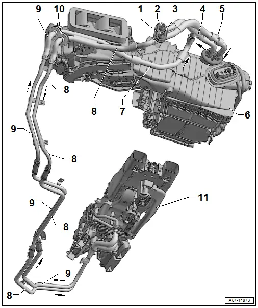
1 - Openings through the Lower Plenum Chamber Bulkhead for the Coolant Lines
2 - Coolant Return to Engine
- Heating and A/C system integration into the engine coolant circuit. Refer to → Chapter "Incorporation of Front Heating and A/C System into Coolant Circuit, Vehicles without a Parking Heater" and → Rep. Gr.19; Coolant System/Coolant; Connection Diagram - Coolant Hoses.
3 - Coolant Supply from Engine
- Heating and A/C system integration into the engine coolant circuit. Refer to → Chapter "Incorporation of Front Heating and A/C System into Coolant Circuit, Vehicles without a Parking Heater" and → Rep. Gr.19; Coolant System/Coolant; Connection Diagram - Coolant Hoses.
4 - Coolant Hose, "Return"
- Coolant return to engine
- Inside the plenum chamber
5 - Bleed Screw in the "Supply" Coolant Hose
- Coolant supply from engine
- Inside the plenum chamber
- Refer to → Chapter "Coolant Circuit, Bleeding"
6 - Front Heater and A/C Unit
- Heat exchanger, removing and Installing with the heater and A/C unit installed. Refer to → Chapter "Heater Core, Removing and Installing".
- Heat exchanger, removing and Installing with the heater and A/C unit removed. Refer to → Chapter "Overview - Heater and A/C Unit".
7 - Coolant Lines and Coolant Hoses from the Heater Core inside the Rear Heater and A/C Unit
- Inside the plenum chamber
- Return from the rear heater and A/C unit to the engine
8 - Coolant Lines and Coolant Hoses to the Heater Core to the Heater Core inside the Rear Heater and A/C Unit
- In the plenum chamber, in the right wheel housing and on the underbody
- Supply from engine to the rear heater and A/C unit
- Pay attention to the correct routing, securing and incorporation of the coolant pipes and coolant hoses from the openings of the plenum chamber other the area under the right fender and on the underbody of the vehicle to the heat exchanger in the rear heater and A/C unit.
9 - Coolant Lines and Coolant Hoses to the Heater Core from the Heater Core inside the Rear Heater and a/C Unit
- In the right wheel housing and on the underbody
- Return from the rear heater and A/C unit to the engine
- Pay attention to the correct routing, securing and incorporation of the coolant pipes and coolant hoses from the openings of the plenum chamber other the area under the right fender and on the underbody of the vehicle to the heat exchanger in the rear heater and A/C unit.
10 - Openings in the Area under the Right Fender for the Coolant Lines
- Pay attention to the correct routing, securing and incorporation of the coolant pipes and coolant hoses from the openings of the plenum chamber other the area under the right fender and on the underbody of the vehicle to the heat exchanger in the rear heater and A/C unit.
11 - Rear Heater and A/C Unit with Heat Exchanger
- To the coolant pipes to the heater core on the rear heater and A/C unit (in the passenger compartment).
 Note
Note
- The coolant pipes to the heat exchanger, via which the coolant hoses are connected are a component of the rear heater and A/C unit.
- For the refrigerant lines to be removed, the right aerodynamic underbody trim and the heat shield in the center tunnel must first be removed. Refer to → Body Exterior; Rep. Gr.66; Moldings, Trims, Extensions and Trim Panels; Floor Heat Shield, Removing and Installing.
- For these coolant lines to the heat exchanger to be able to be removed, the air duct to the Rear Fresh Air Blower -V80- (Refer to → Chapter "Rear Fresh Air Blower -V80-, Removing and Installing".) and the heat shield in the center tunnel must be removed. Refer to → Body Exterior; Rep. Gr.66; Moldings, Trims, Extensions and Trim Panels; Floor Heat Shield, Removing and Installing.
- The coolant lines to the heater core in the rear heater and A/C unit are connected via coolant hoses, which are routed in the center tunnel above the driveshaft over the heat shield, to the coolant circuit.
- To remove the heat shield in the center tunnel, the exhaust system with the center muffler and the driveshaft must additionally be removed depending on the vehicle. Refer to → Rear Final Drive 0D2, 0D3, 0DB; Rep. Gr.39; Driveshaft; Driveshaft, Removing and Installing.

