Audi Q7: Infotainment System Display, Removing and Installing
The Front Information Display Control Head -J685- (Display Infotainment system) is located in the center of the instrument panel.
Removing
The display must be retracted before removing it. If the display can no longer be retracted due to a defect, the display can be manually retracted. To do so, exert pressure on the slip clutch by hand and push the display in.
- Turn off the ignition and all electrical equipment and remove the ignition key.
- Remove the center air duct. Refer to → Heating, Ventilation and Air Conditioning; Rep. Gr.87; Air Routing.
By removing the center air duct the bolts for the kinematics are accessible.
 Caution
Pay attention to the wire routing to the display in the instrument panel. It will not be possible to extend the display again if the wiring is routed incorrectly during installation.
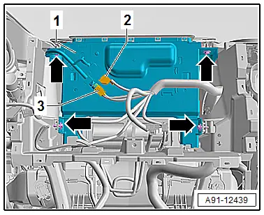
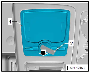
- Unlock and disconnect the connectors -2 and 3-.
- Remove the bolts -arrows- and remove the Front Information Display Control Head -J685--1- from the instrument panel.
Installing
- Install in reverse order of removal. Note the following:
- Make sure that the wiring guide of the Front Information Display Control Head -J685- to the wiring harness is followed exactly, otherwise the Front Information Display Control Head -J685- will not extend out.
Tightening Specifications
- Refer to → Chapter "Component Location Overview - Infotainment System"
Information Electronics Control Module 1 -J794-, Removing and Installing
The Information Electronics Control Module 1 -J794- is located in the glove compartment.
Special tools and workshop equipment required
- Radio Removal Tool -T10057-
- Fiber-Optic Repair Set - Connector Protective Caps -VAS6223/9-.
 Note
Note
If replacing the control module, select the "Replace control module" function for the corresponding control module. Refer to Vehicle Diagnostic Tester.
Removing
- Open the glove compartment.
- Remove any CD/DVDs and SD/SIM cards from the Information Electronics Control Module 1 -J794-.
- Turn off the ignition and all electrical equipment and remove the ignition key.
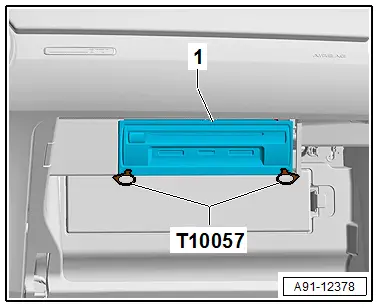
- Insert the two clips from the Radio Removal Tool -T10057- into the slits in the Information Electronics Control Module 1 -J794--1- until they lock into place. The points on the gripping eyelets face outward.
- Remove the Information Electronics Control Module 1 -J794--1- from the glove compartment at the Radio Removal Tool -T10057- grip eyes.
- Release and disconnect the connectors from the Information Electronics Control Module 1 -J794--1-.
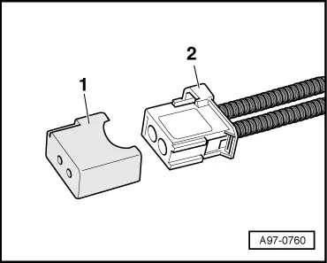
- Insert the Fiber-Optic Repair Set - Connector Protective Caps -VAS6223/9--1- onto the MOSTBusconnector -2-.
- Press the release tabs on the Information Electronics Control Module 1 -J794- and remove the Radio Removal Tool -T10057-.
Installing
- Install in reverse order of removal. Note the following:
- Connect all the connectors.
- Insert the Information Electronics Control Module 1 -J794- until it engages in the glove compartment.
Multimedia System Control Head -E380-, Removing and Installing
Multimedia System Control Head -E380-, Removing and Installing
The Multimedia System Control Head -E380- (QW1) is located in the center console at the front.
Removing
- Turn off the ignition and all electrical equipment and remove the ignition key.
Multimedia Control Head -E380- is attached to the center console.
 Caution
The surfaces can get scratched very easily.
Carefully mask all surfaces and sections!
- Remove the center console insert. Refer to → Body Interior; Rep. Gr.68; Center Console; Center Console Insert, Removing and Installing.
- Remove the center console insert trim. Refer to → Body Interior; Rep. Gr.68; Center Console; Display Control Head Trim, Removing and Installing.
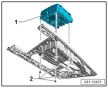
- Release and disconnect the connector from the back of the Multimedia System Control Head -E380-.
- Remove the bolts -2- and the Multimedia System Control Head - E380--1- upward from the center console insert.
Installing
- Install in reverse order of removal.
Tightening Specifications
- Refer to → Chapter "Component Location Overview - Infotainment System"
Touchpad Control Module -J929-, Removing and Installing, UJ1
The Touchpad Control Module -J929- (UJ1) is located on the bottom of the Multimedia System Control Head -E380-. It cannot be replaced alone.
If faulty, then the Multimedia System Control Head -E380- must be replaced. Refer to → Chapter "Multimedia System Control Head -E380-, Removing and Installing".
Control Knob Cover, Replacing
If the cover of the control knob (Multimedia System Control Head -E380-) is damaged or scratched, it can be replaced using a replacement part kit.
- Replacement part kit. Refer to the Parts Catalog.
Removing
- Turn off the ignition and all electrical equipment and remove the ignition key.
To remove the cover an adhesive strip from the replacement part kit is used.
- First clean the cover thoroughly. Remove the protective film from the adhesive strip.
- Push the adhesive strip -2- on the cover using thumbs.
- After a wait time of five seconds the cover can be removed vertically upward in a jerking manner in direction of -arrow-. Make sure that when removing that the control knob on the chrome ring is counterheld.
Installing
- Place the new cover on the control knob and press in carefully using a towel.
- Make sure that the centering tab on the cover is seated correctly on the control knob.

