Audi Q7: A/C System Temperature Door Heat Output Activation, Checking
 Note
Note
- Depending on vehicle equipment, there are different versions of the A/C system for the Audi Q7. Make sure to use the correct version and pay attention to the allocation of different components. Refer to → Chapter "A/C System Versions" and Parts Catalog.
- For vehicles with a "Low" A/C system, there is no Rear A/C Display Control Head -E265-, no rear air distribution housing and no rear heater and A/C unit installed.
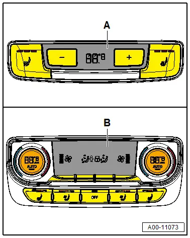
- For vehicles with a "Mid" or "Mix" A/C system, a Rear A/C Display Control Head -E265- version -A- and a rear air distribution housing are installed (but no rear heater and A/C unit). Refer to → Chapter "Rear A/C Display Control Head -E265-, Removing and Installing, High A/C System".
- For vehicles with a "High" A/C system, a Rear A/C Display Control Head -E265- version -B- and a rear heater and A/C unit are installed. Refer to → Chapter "Rear A/C Display Control Head -E265-, Removing and Installing, High A/C System".
- On a vehicle with a "Low" A/C system (without a Rear A/C Display Control Head -E265-, without an air distribution housing and a rear heater and A/C unit) the temperature of the air which flows from the front heater and A/C unit to the rear vent is regulated from the Front A/C Display Control Head -E87- so that the air out of the vent for the front area has an average temperature. The target temperature for the air from the vents in the front area is calculated via the setting for the left and right side on the Front A/C Display Control Head -E87- from the Front A/C Display Control Head -E87-. However, if a setting which no longer regulates the temperature (for example, "HI" for maximum heating or "LO" for maximum cooling) is present on the Front A/C Display Control Head -E87-, the temperature of the air from the vents in the front area is no longer regulated. If, for example, maximum heating "HI" is set on the Front A/C Display Control Head -E87- for one side and maximum cooling "LO" for the other side, the air for the vents in the front area is maximally heated.
- On a vehicle with a "Mid" or "Mix" A/C system (with a version -A-Rear A/C Display Control Head -E265-, and an air distribution housing but without a rear heater and A/C unit) the temperature of the air which flows from the front heater and A/C unit to the rear air distribution housing is regulated from the Front A/C Display Control Head -E87- so that the air out of the vent for the front area has an average temperature. The target temperature for the air from the vents in the front area is calculated via the adjustment for the left and right side on the Front A/C Display Control Head -E87- and the adjustment Rear A/C Display Control Head -E265- from the Front A/C Display Control Head -E87-. However, if a setting which no longer regulates the temperature (for example, "HI" for maximum heating or "LO" for maximum cooling) is present on the Front A/C Display Control Head -E87-, the temperature of the air from the vents in the front area is no longer regulated. If, for example, maximum heating "HI" is set on the Front A/C Display Control Head -E87- for one side and maximum cooling "LO" for the other side depending on the adjustment on the Rear A/C Display Control Head -E265- the air for the vents in the front area is maximally heated or cooled.
- Certain A/C system functions can be switched on and off via the MMI (Multi Media Interface) in the "A/C system" function under the "Car"/"Vehicle" menu. The A/C system control can also be influenced via the presets in the MMI (Multi Media Interface) under the "A/C system" function in the "Car"/"Vehicle" menu. Therefore, check the preset in the MMI first in the case there is a problem with these components. Refer to Infotainment/MMI Operating Instructions.
Special tools and workshop equipment required
- Vehicle Diagnostic Tester with the "Guided Fault Finding" function and the corresponding connection lines. Refer to Workshop Equipment.
- A standard thermometer (for temperature measurement; if necessary, a thermometer with two measuring probes for simultaneous measurement, for example, for temperature on the right and left)
If the coolant circuit is not completely bled after filling, air may collect in the front heater and A/C unit heater core (and the rear heater and A/C unit, if equipped), which reduces the heat output. There may also be noise or the customer may complain of different air temperatures flowing out of the vents on the driver side and front passenger side (front and rear, left and right rear) at the same setting.
Corrective Measure:
- Check the coolant circuit and bleed it again if necessary. Refer to → Chapter "Coolant Circuit, Bleeding".
- If it is suspected that air remains in the cooling system after the bleeding operation. Perform a lengthy test drive at high engine speed (at least 10 minutes, engine speed above 2500 rpm). Select a low gear during the test to prevent excessive vehicle speed.
In the event of a customer complaint regarding poor heating output at certain engine speeds:
- Check the incorporation of the heat exchanger in the front heater and A/C unit (and in the rear heater and A/C unit if present) into the coolant circuit. If for example the two coolant hoses (supply and return) of the engine are interchanged, the coolant is flowing in the wrong direction through the heater core. It is also possible that the Coolant Recirculation Pump -V50- is working against the engine coolant pump. Refer to → Chapter "Incorporating the Heating and A/C System in the Coolant Circuit" and → Rep. Gr.19; Coolant System/Coolant; Connection Diagram - Coolant Hoses.
If a different air temperature is coming out of the vents during A/C system control mode, it may be caused by the following.
- One or more temperature doors in the front heater and A/C unit (or in the rear heater and A/C unit if present) does not close completely or does not reach its end position.
- There is air in the front heater and A/C unit heater core (of the rear heater and A/C unit). This results in fluctuating flows through the affected heater core and the heat is not distributed uniformly.
- When installing the heat exchanger the foam seal has loosened and air may flow past the heat exchanger (refer to → Chapter "Heater Core, Removing and Installing") (front heater and A/C unit) (and refer to → Chapter "Heater Core, Removing and Installing") (heat exchanger in the rear heater and A/C unit).
- The A/C system refrigerant circuit is not filled with the correct quantity of refrigerant (perform a cooling output test). Refer to → Chapter "Cooling Output, Checking".
 Note
Note
- A start-stop system is available as optional equipment for certain engines of this vehicle. Depending on the setting on the Front A/C Display Control Head -E87- (or if present at the Rear A/C Display Control Head -E265-) it can prevent the stop function. If, for example, the "defrost" mode is selected on the Front A/C Display Control Head -E87-, the stop function is not possible or will be interrupted and the engine will start as soon as this operating mode is selected. The same also applies if the difference between the selected specified temperature and the measured actual temperature exceeds a certain value in heating and cooling mode. Refer to Vehicle Diagnostic Tester in the "Guided Fault Finding" function.
- In vehicles with a start-stop system, the Coolant Recirculation Pump -V50- (the Recirculation Pump -V55- of the parking heater) is activated even when the stop function is active in order to maintain the coolant flow through the heat exchanger. Refer to → Chapter "Component Location Overview - Rear Components Outside of Passenger Compartment". Refer to Vehicle Diagnostic Tester in the "Guided Fault Finding" function.
Heater and A/C Unit, Removing and Installing
Special tools and workshop equipment required
- Hose Clamps - Up To 25mm -3094- and Hose Clamps - Up To 40mm -3093-
- Commercial compressed-air gun with rubber end piece
- Cooling System Tester -VAG1274B- (and corresponding adapters)
 Note
Note
- Depending on vehicle equipment, there are different versions of the A/C system for the Audi Q7. Make sure to use the correct version and pay attention to the allocation of different components. Refer to → Chapter "A/C System Versions" and Parts Catalog.
- When removing, record the bolt lengths and allocation for the reinstallation.
- All cable ties and other wiring harness fasteners released or cut open when removing the heater and A/C units are to be re-attached in same position on installation.
Removing
- Turn off the ignition.
- Discharge the refrigerant circuit. Refer to → Refrigerant R134a Servicing; Rep. Gr.87; Refrigerant Circuit.
- Remove the plenum chamber cover. Refer to → Body Exterior; Rep. Gr.50; Bulkhead; Plenum Chamber Cover, Removing and Installing.
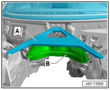
- Remove the tower brace -A-. Refer to → Suspension, Wheels, Steering; Rep. Gr.40; Suspension Strut and Upper Control Arm; Tower Brace, Removing and Installing.
- Loosen the lower plenum chamber bulkhead -B- from the vehicle and move to the side (do not remove). Refer to → Body Exterior; Rep. Gr.50; Bulkhead; Overview - Bulkhead.
 WARNING
There is a risk of scalding from hot steam and coolant.
- The cooling system is under pressure when the engine is warm.
- To reduce the pressure, cover the coolant reservoir cap with cloths and then open it carefully.
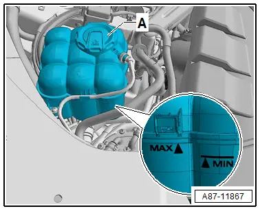
- Carefully open the coolant expansion tank cap -A- (do not completely remove).
 Note
Note
There are different versions of the coolant expansion tank and in different allocations in the engine compartment. Refer to → Rep. Gr.19; Coolant System/Coolant; Coolant, Draining and Filling.
- Label the arrangement of the coolant hoses at the connections to the heater core -A- (supply from the Coolant Recirculation Pump -V50-) and -B- (return to the engine).
 Note
Note
- The heat exchanger is installed in the heater and A/C unit so that a specific flow direction of the coolant is necessary for clean bleeding of the heater core. Therefore, the coolant hoses must be connected on the correct side. Refer to → Chapter "Incorporating the Heating and A/C System in the Coolant Circuit".
- Bleed the coolant circuit. Refer to → Chapter "Coolant Circuit, Bleeding" and → Rep. Gr.19; Coolant System/Coolant; Coolant, Draining and Filling.
 Note
Note
There are different versions of the coolant expansion tank and in different allocations in the engine compartment. Refer to → Rep. Gr.19; Coolant System/Coolant; Coolant, Draining and Filling.
- Label the arrangement of the coolant hoses at the connections to the heater core -A- (supply from the Coolant Recirculation Pump -V50-) and -B- (return to the engine).
 Note
Note
- The heat exchanger is installed in the heater and A/C unit so that a specific flow direction of the coolant is necessary for clean bleeding of the heater core. Therefore, the coolant hoses must be connected on the correct side. Refer to → Chapter "Incorporating the Heating and A/C System in the Coolant Circuit".
- Bleed the coolant circuit. Refer to → Chapter "Coolant Circuit, Bleeding" and → Rep. Gr.19; Coolant System/Coolant; Coolant, Draining and Filling.
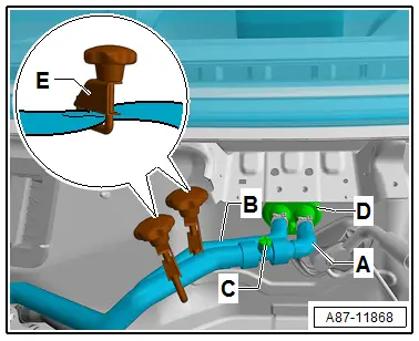
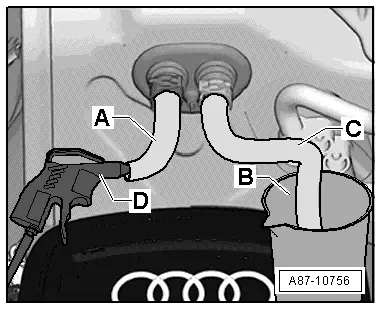
- Clamp the coolant hoses -A and B- with hose clamps -E-.
- Cover the area beneath connections for coolant hoses -A and B-, for example with absorbent paper.
- Place a small container under the connections for coolant hoses -A and B- (to the heater core).
 Note
Note
To prevent coolant from entering the plenum chamber when removing coolant hoses -A and B-.
- Remove the coolant hoses -A and B- from the connections to the heater and A/C unit heater core.

- Insert one section each of hose -A and B- on to both connections to heater core.
- Place a container -B- under the other end of the hose -C- .
- Using a compressed air gun -D-, carefully blow coolant out of the heater core against the normal flow direction of the coolant) via shaft -A- into container -B-.
- Disconnect the refrigerant lines -A and C- from the front expansion valve -D- and put aside (do not remove). Refer to → Chapter "Refrigerant Lines, Disconnecting from Front Expansion Valve and Reconnecting".
 Note
Note
Immediately seal off any open line connections and connection points with clean plugs, for example, taken from the Engine Bung Set -VAS6122-.
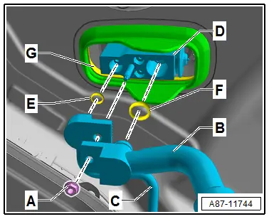
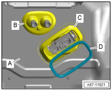
- Loosen the grommet with the support ring -D- from the plenum chamber rear wall toward the passenger compartment (it is removed and installed with the heater and A/C unit).
- Vehicles with a "Mid", "Mix" or "High" A/C system, remove the rear heater and A/C unit. Refer to → Chapter "Heater and A/C Unit, Removing and Installing, High A/C System".
- Remove the instrument panel central tube. Refer to → Body Interior; Rep. Gr.70; Instrument Panel Central Tube; Instrument Panel Central Tube, Removing and Installing.
 Caution
A/C system malfunctions in the case of interchanged control motors and/or connectors. Refer to → Chapter "Main Wiring Diagram for A/C System Actuators".
- The adjustment motors and connectors are identical. If they are installed or connected incorrectly, the corresponding doors cannot be properly adapted and/or activated.
- Clearly label the actuators and connectors prior to removal to prevent incorrect installation.
- Vehicles with a "Low" A/C system, remove the rear air duct. Refer to → Chapter "Air Ducts and Vents in the Rear Vehicle Interior, Low A/C System".
- On vehicles with a Auxiliary Heater Control Module -J604- with Auxiliary Heater Heating Element -Z35-, disconnect the connector -A- and remove the connections -C- (positive) and -B-.
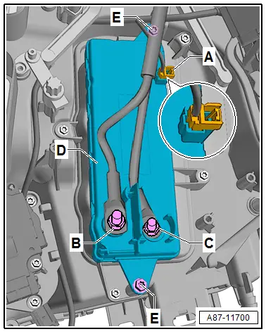
- Remove both condensation water drains -A- from the connections -B- on the heater and A/C unit.
 Note
Note
The "A/C system "wiring harness is removed with the heater and A/C unit.
- Cover the floor covering in the area of the center tunnel with a mat.
- Free up the wiring harness -F-.
- Remove the grommet -E- for the coolant pipes to the heat exchanger and grommet -D- for the expansion valve from the openings in the rear wall of the plenum chamber and carefully detach the heater and A/C unit -C- (so that no components are damaged by any still attached connections) slightly from the vehicle and remove it in the direction of the front passenger footwell.
Installing
Install in reverse order of removal. Note the following:
 Note
Note
Before installing, check all gaskets and grommets on the heater and A/C unit for damage and replace if necessary.
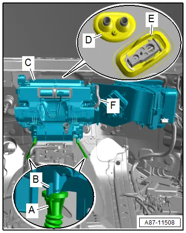
- Coat the grommet -B and C- with grease and install it in the plenum chamber rear wall -A-.
- Install the support ring -D- in the grommet.
- Check the position of the coolant and refrigerant lines in both grommets in the plenum chamber rear wall, and if necessary, align the heater and A/C unit so that the lines are not tensioned in the grommets.
 Note
Note
When installing air ducts ensure proper seating and leak-proof connection of the components. If the connection points are not leak-proof, noises can result from escaping air or the escaping warm or cold air can affect the regulation of the A/C system.
- Remove the refrigerant line from the front expansion valve. Refer to → Chapter "Refrigerant Lines, Disconnecting from Front Expansion Valve and Reconnecting".
- Install both coolant hoses -A and B- on the coolant pipes to the heater core in the front heater and A/C unit bleed the coolant circuit as described with the engine off, and check for leaks. Refer to → Chapter "Heater Core, Removing and Installing" and → Chapter "Heater Core, Removing and Installing".
- Bleed the heat exchanger in the heater and A/C unit. Refer to → Chapter "Heater Core, Removing and Installing" and → Chapter "Heater Core, Removing and Installing".

 Note
Note
When installing the instrument panel, make sure that the "defrost" intermediate piece its properly on heater and A/C unit and the defroster vent does not pinch the intermediate piece. Refer to → Chapter "Overview - Air Routing and Air Distribution in Passenger Compartment, Front".
- Evacuate and charge the refrigerant circuit. Refer to → Refrigerant R134a Servicing; Rep. Gr.87; Refrigerant Circuit.
- Perform the basic setting and the output diagnostic test mode of the A/C system. Refer to Vehicle Diagnostic Tester in the "Guided Fault Finding" function.
 Note
Note
- In this vehicle, the actuators are equipped with electronics. During the basic setting, a new control motor learns its position on the heater and A/C unit and can then be activated by the Front A/C Display Control Head -E87- (currently all actuators are identical). Refer to Vehicle Diagnostic Tester in the "Guided Fault Finding" function.
- During the basic setting, the actuators are assigned and adapted corresponding to the switching sequence of the wiring. If this sequence does not conform with the specification, the actuators will adapt incorrectly and the door control will be wrong. Refer to → Chapter "Main Wiring Diagram for A/C System Actuators".
- Check the DTC memory on the Front A/C Display Control Head -E87- and erase any displayed malfunctions. Refer to Vehicle Diagnostic Tester in the "Guided Fault Finding" function.
- Operate the A/C system after charging the refrigerant circuit. Refer to → Chapter "A/C System, Starting after Charging Refrigerant Circuit".
 Note
Note
Note the information regarding operating the A/C system after filling. Refer to → Refrigerant R134a Servicing; Rep. Gr.87; A/C System, General Information.

