Audi Q7: Engine Oil Cooler
Overview - Engine Oil Cooler
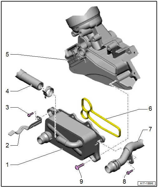
1 - Engine Oil Cooler
- With oil cooler bypass valve
- See note.
- Removing and installing. Refer to → Chapter "Engine Oil Cooler, Removing and Installing".
2 - Bracket
3 - Bolt
- 3 Nm +90Âş
- Replace after removing
4 - Coolant Hose
5 - Lower Timing Chain Cover
6 - Seal
- Replace after removing
7 - Upper Coolant Pipe
- Removing and installing. Refer to → Chapter "Upper Coolant Pipe, Removing and Installing".
8 - Bolt
- Tightening specification. Refer to -item 19-.
9 - Bolt
- 3 Nm +90Âş
- Replace after removing
Engine Oil Cooler, Removing and Installing
Special tools and workshop equipment required
- Hose Clip Pliers -VAS6362-
 Caution
This procedure contains mandatory replaceable parts. Refer to component overview prior to starting procedure.
Mandatory Replacement Parts
- Bolts - Engine oil cooler
- Seal - Engine oil cooler
Removing
- Drain the coolant. Refer to → Chapter "Coolant, Draining and Filling".
- Remove the Coolant Recirculation Pump -V50- with bracket. Refer to → Chapter "Coolant Recirculation Pump -V50-, Removing and Installing".
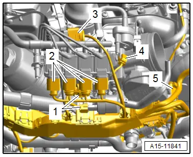
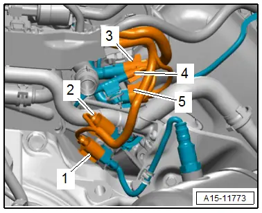
- Disconnect the connectors -1 to 5- and free them up.
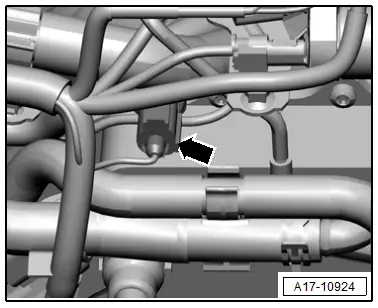
- Disconnect the connector -arrow- for the Oil Pressure Switch -F22- and free up the wire.
- Disconnect the connectors -1 through 5- and remove them from the bracket.
- Free up the wiring harness.
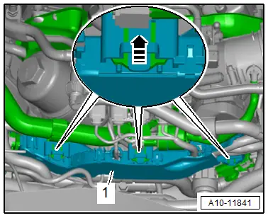
- Release the catches in direction of -arrow-, remove the wiring duct -1- toward the rear and push to the side.
- Push the wires and hoses to the side.
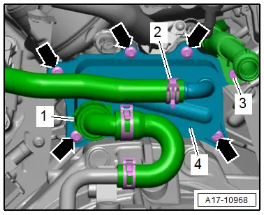
- Lift the clamp -1-, loosen the hose clamp -2- and remove the coolant hoses.
- Remove the bolts -3 and arrows- and remove the engine oil cooler -4- to the left side.
Installing
Install in reverse order of removal and note the following:
 Note
Note
- Replace the bolts that were tightened with an additional turn after removing them.
- Replace the seal after removal.
- Secure all hose connections with hose clamps that match the ones used in series production. Refer to the Parts Catalog.
- Connections and wire routing. Refer to → Wiring diagrams, Troubleshooting & Component locations.
- Connect the coolant hoses with the connector coupling. Refer to → Fig. "Connect the Coolant Hose to the Connector Coupling".
 Note
Note
Used coolant cannot be used again.
- Fill with coolant.
Tightening Specifications
- Refer to → Chapter "Overview - Oil Pan/Oil Pump"
- Refer to → Chapter "Overview - Electric Coolant Pump"

