Audi Q7: Overview - Air Lines
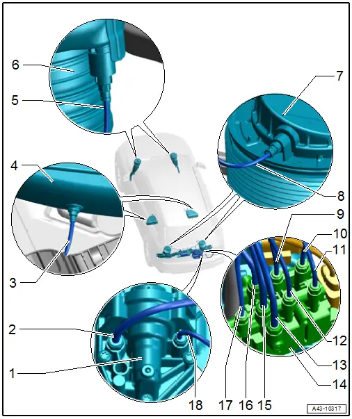
1 - Air Supply Unit with Level Control System Compressor Motor -V66-
- Overview. Refer to → Chapter "Overview - Air Supply Unit".
2 - Air Line "Brown"
- To solenoid valve block
- Connector tightening specification 3 Nm
3 - "Purple" Air Line
- Connecting piece tightening specification 5 Nm
- From the solenoid valve
4 - Pressure Reservoir
- Removing and installing. Refer to → Chapter "Pressure Reservoir, Removing and Installing".
5 - Air Line
- Connector tightening specification 2 Nm
- Left "red", right "green"
- From the solenoid valve
- Front air line routing. Refer to → Fig. "Air Line Routing to the Front Air Spring"
- Do not loosen the residual pressure valve
6 - Front Air Spring
7 - Rear Air Spring
8 - Air Line
- Connector tightening specification 2 Nm
- Left "black", right "blue"
- From the solenoid valve
- If there is a damage claim replace completely. The repair of a damaged air line is not permitted.
- Rear air line routing. Refer to → Fig. "Air Line Routing on the Subframe to the Rear Air Spring"
9 - "Green" Air Line
- Connector tightening specification 2 Nm
- To the right front air spring
10 - "Blue" Air Line
- Connector tightening specification 2 Nm
- To the right rear air spring
11 - "Black" Air Line
- Connector tightening specification 2 Nm
- To the left rear air spring
12 - "Red" Air Line
- Connector tightening specification 2 Nm
- To the left front air spring
13 - "Purple" Air Line
- Connector tightening specification 3.6 Nm
- To the right pressure reservoir
14 - Solenoid Valve Block
15 - "Purple" Air Line
- To the left pressure reservoir
- Connector tightening specification 3.5 Nm
16 - Air Line "Brown"
- From the air supply unit
- Connector tightening specification 3.5 Nm
17 - Air Line "Brown"
- To the air supply unit
- Connector tightening specification 2 Nm
18 - Air Line "Brown"
- From the solenoid valve
- Connector tightening specification 2 Nm
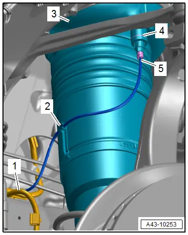
Air Line Routing to the Front Air Spring
- Contains the air line -5- on the Clip -2- in the wiring harness -1-.
3 - Front Air Spring
4 - Residual Pressure Retaining Valve - Do Not Loosen
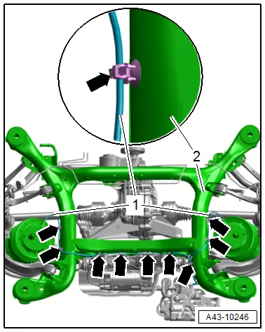
Air Line Routing on the Subframe to the Rear Air Spring
- Secure the air line -1- with the clips -arrows- on the subframe -2- as shown.
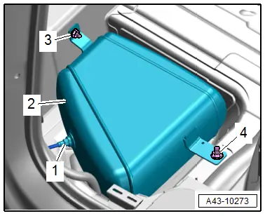
Pressure Reservoir - Tightening Specification
- Tighten the bolt -3- and nut -4- to 6 Nm.
Overview - Air Supply Unit
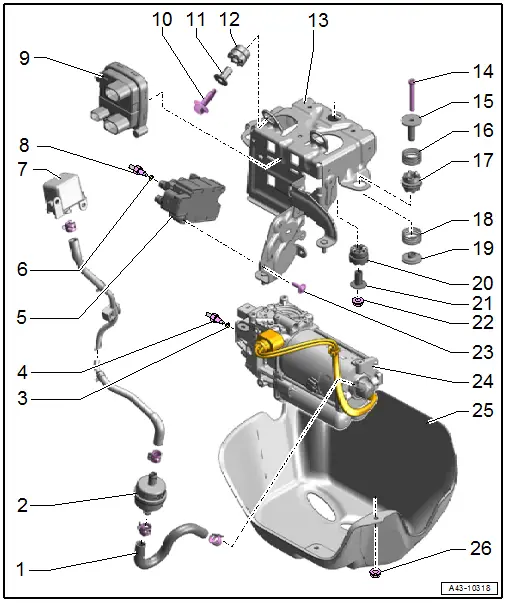
1 - Hose
2 - Filter
- Removing and installing. Refer to → Chapter "Filter, Removing and Installing".
3 - O-Ring
- Replace after removing
4 - Air Line
- Air lines overview. Refer to → Chapter "Component Location Overview - Air Suspension"
- Connecting piece tightening specification. Refer to → Chapter "Overview - Air Lines".
5 - Solenoid Valve Block
- Line arrangement. Refer to → Chapter "Overview - Air Lines".
- Removing and installing. Refer to → Chapter "Solenoid Valve Block, Removing and Installing".
6 - O-Ring
- Replace after removing
7 - Muffler
- Component location in the interior (spare tire well)
8 - Air Line
- Air lines overview. Refer to → Chapter "Component Location Overview - Air Suspension"
- Connecting piece tightening specification. Refer to → Chapter "Overview - Air Lines".
9 - Compression Control Module
- Removing and Installing. Refer to → Chapter "Level Control System Compressor Electronics -J1135-, Removing and Installing".
10 - Bolt
- 9 Nm
- Quantity: 2
11 - Spacer Sleeve
12 - Grommet
13 - Bracket
- For the air supply unit
14 - Bolt
- 5 Nm
15 - Spacer Sleeve
16 - Spring
17 - Grommet
18 - Spring
19 - Spring Support
20 - Grommet
21 - Spacer Sleeve
22 - Nut
- 9 Nm
23 - Bolt
- 3.5 Nm
24 - Air Supply Unit with Level Control System Compressor Motor -V66-
- Removing and installing. Refer to → Chapter "Air Supply Unit, Removing and Installing".
25 - Cover
26 - Nut
- 9 Nm

