Audi Q7: Peripheral Camera Control Module -J928-, Removing and Installing
The Peripheral Camera Control Module -J928- is located behind the left luggage compartment trim panel.
 Note
Note
If replacing the control module, select the "Replace control module" function for the corresponding control module. Refer to Vehicle Diagnostic Tester.
Removing
- Turn off the ignition and all electrical equipment and remove the ignition key.
- Remove the left luggage compartment side trim panel. Refer to → Body Interior; Rep. Gr.70; Luggage Compartment Trim Panels; Luggage Compartment Side Trim Panel, Removing and Installing.
- Remove the Relay and Fuse Panel 4 - SR4-. Refer to → Electrical Equipment; Rep. Gr.97; Relay Panels, Fuse Panels and E-Boxes; Component Location Overview - Relay Panels, Fuse Panels and E-Boxes.
Do not disconnect the connectors.
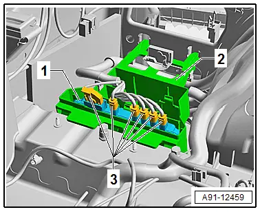
The Peripheral Camera Control Module -J928--1- is only clipped to the bracket -2-.
- Unlock and disconnect the connectors -3- from the Peripheral Camera Control Module -J928--1-.
- Press the retainer downward and remove the Peripheral Camera Control Module -J928--1- from the bracket -2-.
Installing
- Install in reverse order of removal.
- Perform a calibration. Refer to → Chapter "Peripheral Camera, Calibrating".
Tightening Specifications
- Refer to → Chapter "Component Location Overview - Peripheral Camera"
Rear Peripheral Camera -R246-, Removing and Installing
The Rear Peripheral Camera -R246- is installed in the rear lid handle button. It is permanently attached to the button.
The handle button must be replaced when replacing the Rear Peripheral Camera -R246-.
Removing
- Turn off the ignition and all electrical equipment and remove the ignition key.
The Rear Peripheral Camera -R246- has a trailing cable. The vehicle wiring harness couplings are located in the rear lid.
- Remove the lower rear lid trim panel. Refer to → Body Interior; Rep. Gr.70; Luggage Compartment Trim Panels; Rear Lid Lower Trim Panel, Removing and Installing.
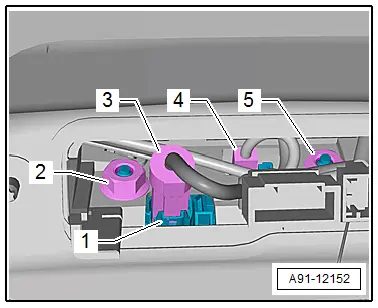
- Release and disconnect the connectors -3 and 4- from the rear lid handle button.
The Rear Peripheral Camera -R246--1- is permanently attached to the handle button.
- Remove the nuts -2 and 5-.
- Pull the handle button with the Rear Peripheral Camera -R246--1- out of the retainer in the rear lid.
Installing
- Install in reverse order of removal.
- Close the rear lid.
The Rear Peripheral Camera -R246- must be programmed again prior to calibrating if it was replaced.
Use the Vehicle Diagnostic Tester.
- Perform a calibration. Refer to → Chapter "Front Peripheral Camera -R243-, Removing and Installing".
Tightening Specifications
- Refer to → Chapter "Component Location Overview - Peripheral Camera"
Front Peripheral Camera -R243-, Removing and Installing
The Front Peripheral Camera -R243- is installed in the radiator grille between the Audi rings.
Removing
- Turn off the ignition and all electrical equipment and remove the ignition key.
- Remove the lock carrier cover. Refer to → Body Exterior; Rep. Gr.63; Front Bumper; Overview - Bumper Cover.
- Remove the mounting bracket with the release cable for the operating lever hook and move it to the side. Refer to → Body Exterior; Rep. Gr.55; Hood; Overview - Release Cable.
- Depending on vehicle equipment, remove the upper air duct for better accessibility. Refer to → Rep. Gr.19; Radiator/Radiator Fan; Overview - Radiator/Radiator Fan.
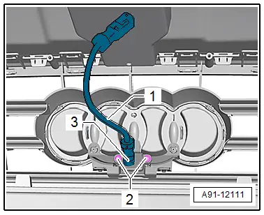
- Remove the screws -2- on the Front Peripheral Camera -R243--3-.
- Remove the Front Peripheral Camera -R243--3- from the radiator grille.
- Release and disconnect the wire -1- from the Front Peripheral Camera -R243--3-.
Installing
- Install in reverse order of removal.
The Front Peripheral Camera -R243- must be programmed again prior to calibrating if it was replaced.
Use the Vehicle Diagnostic Tester.
- Perform a calibration. Refer to → Chapter "Peripheral Camera, Calibrating".
Tightening Specifications
- Refer to → Chapter "Component Location Overview - Peripheral Camera"
Right and Left Peripheral Cameras -R244-/-R245-, Removing and Installing
The left and right peripheral cameras - R244-/- R245- are located in the exterior rearview mirror respectively.
 Note
Note
The removal and installation is described for the left side. Removing and installing on the right side is identical.
Removing
- Turn off the ignition and all electrical equipment and remove the ignition key.
- Remove the exterior rearview mirror turn signal. Refer to → Electrical Equipment; Rep. Gr.94; Lamps in Exterior Rearview Mirror; Turn Signal, Removing and Installing.
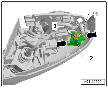
- Remove the bolts -arrows-.
- Remove the Left Peripheral Camera -R244--1- with the bracket -2- from the exterior rearview mirror.
- Release and disconnect the connector -3-.
- Remove the Left Peripheral Camera -R244--1- from the bracket -2-.
Installing
- Install in reverse order of removal.
Tightening Specifications
- Refer to → Chapter "Component Location Overview - Peripheral Camera"

