Audi Q7: Preliminary Check
 Note
Note
- Before performing any pin point test or component diagnosis, a Preliminary Check must be performed.
- Check for Technical Bulletins that may supersede any information included in the repair manual or GST Manual.
- For Electrical Testing.
- For Fuel System Mechanical Testing.
- For Oxygen Sensor Preliminary Tests.
Electrical Testing
Fuel System Mechanical Testing
Check the following items for possible mechanical delivery deficiency:
- Fuel level in tank is too low.
- Fuel lines pinched.
- Fuel filter plugged.
- Fuel pump delivery unit internal leak.
- Clogged injectors.
- Poor fuel quantity delivery. Refer to appropriate repair manual.
Oxygen Sensor Preliminary Tests
Check for the following conditions which can cause Oxygen Sensor Faults to set without requiring Oxygen Sensor replacement:
Common issues for lean faults:
- Vacuum leaks - check for failed or loose vacuum lines, leaking intake gaskets, or any other source of un-metered air leaks (leaks after the Mass Air Flow Sensor).
- Restricted fuel filter or bent/pinched fuel system lines.
- Incorrect input from other sensors, such as the Mass Air Flow Sensor, which may not always set a fault.
- Engine misfire.
- Exhaust leaks.
- Camshaft timing.
- Common issues for rich faults:
- Leaking or faulty fuel injector.
- Fuel injector driver shorted in ECM, or wiring short for injectors (short to ground).
- Leaking or faulty fuel pressure regulator or restricted return line.
- Faulty fuel pump or fuel pump driver module.
- Incorrect input from other sensors, such as the Mass Air Flow Sensor, which may not always set a fault.
- Aftermarket components or performance chips.
- Camshaft timing.
Readiness Code
 Caution
When performing the Readiness drive cycle operation, pay strict attention to driving conditions and observe and obey all posted speed limits.
Readiness code description
Diagnostics are performed at regular intervals during normal vehicle operation. After repairing an emissions related system, a readiness code is generated by road testing the vehicle.
If a malfunction is recognized during the drive cycle, it will be stored in the DTC memory.
The OBD drive cycle operation will be monitored with a hand held diagnostic tool. Consult the manufacturer's instruction manual for correct tool operation.
The readiness code is erased every time the DTC memory is erased or any time the battery is disconnected. If the DTC memory has been erased or the battery is disconnected, a new readiness code must be generated.
Only erase the DTC memory if a DTC has been stored.
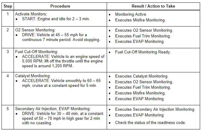
General recommendations
Most monitors will complete easier and quicker using a "steady-foot" and "smooth" acceleration during the drive cycle operation.
Operating conditions
For the EVAP monitor test, the coolant temperature and the ambient air temperature must be between 10º C and 35º C with a difference between them no greater than 4º C. The ambient air temperature must not change more than 4º C during the drive cycle procedure (e.g. when driving out of a heated workshop in the winter).
 Note
Note
Do not assume that the scan tool ID and engine code are correct if the scan tool communicates. The scan tool does not use the ID to establish communication-the units are automatically identified.
Test requirements
- NO DTC in memory.
- Switch OFF all electrical and electronic accessories.
- Necessary driving speed: 50 - 70 mph.
- Drive profile takes approximately 60 - 90 min.
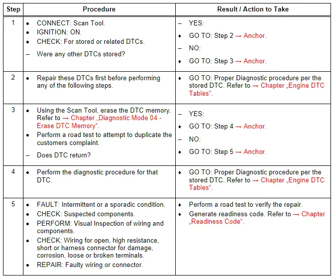
Readiness Drive Cycle Procedure
- CONNECT: Scan Tool.
- If any engine monitor fails the drive cycle test. Repeat the drive cycle test until all engine monitors have successfully run through and passed.
 Note
Note
- When repeating the drive cycle operation for a failed evaporative or thermostat monitor, allow the engine to cool until the coolant temperature and the ambient air temperature are between 10º C and 35º C with a difference between them no greater than 4º C and then repeat the drive cycle operation.
- Depending on the scan tool used, the readiness code status may be displayed as complete, passed or OK. At an ambient air temperature < 7º C, the setting of the readiness for the NOx catalytic converter test is delayed. Here the vehicle must be driven considerably longer.
Readiness Codes and Monitoring Completed
1 - If any engine monitor fails the drive cycle test, repeat the drive cycle test until all engine monitors have successfully run through and passed.
2 - If the drive cycle operation fails again:
3 - Check the DTC memory for stored DTCs.
4 - Repair the vehicle if necessary.
5 - Repeat the drive cycle operation until all engine monitors have successfully run through and passed.
6 - Remove the scan tool and switch the ignition off.

