Audi Q7: Radio
Radio Components
Radio Components, MMI Radio plus, I8E
I8E - MMI Radio plus
- The CD player / SD memory card reader are in the Information Electronics Control Module 1 -J794- inside the glove compartment.
- The Radio -R- is integrated in the Information Electronics Control Module 1 -J794-
- Front Information Display Control Head -J685-, display in center of the instrument panel
- Multimedia System Control Head -E380- in the center console, QW1
- External Audio Source Connection -R199- in the center counsel storage compartment, AUX IN socket/USB Charging
- Soand System: Standard, 9VD
Optional
- Digital Radio -R147- integrated in the Information Electronics Control Module 1 -J794-, only Europe/Rest of World and QV3
- Radio System, Satellite - R146- integrated in the Information Electronics Control Module 1 - J794-, only USA and QV3
- DVD Changer -R161- in the luggage compartment on the left rear side, 6G2
- External Audio Source Connection -R199- in the center console storage compartment, UF7
- Soand System: BOSE, 9VS
- Digital Soand System Control Module -J525- in the luggage compartment
- Bluetooth interface, 9ZX
- Audi phone box, 9ZE
- Voice recognition system, QH1
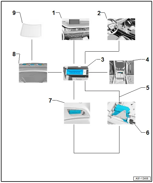
1 - Front Information Display Control Head -J685- in center of the instrument panel
2 - Multimedia System Control Head -E380- in the center console
3 - Information Electronics Control Module 1 -J794- in the glove compartment
4 - External Audio Source Connection -R199- in the center console storage compartment
5 - MOST Bus
6 - Digital Soand System Control Module -J525- in the luggage compartment
7 - DVD Changer -R161- in the luggage compartment on the left rear side
8 - Antenna amplifier inside the rear lid
9 - Antenna -R11-/Radio Antenna 2 -R93- in the rear window
Fault Finding is performed using the "Guided Fault Finding" on the Vehicle Diagnostic Tester -f-.
Notes on MOST Bus
The optical data Bus "MOST Bus" is used in addition to the CAN Bus.
A fiber-optic cable is used. Fiber optic cables are routed inside corrugated tubes for protection.
Replace the complete fiber optic cable if possible.
The front surface of the connectors must not be contaminated.
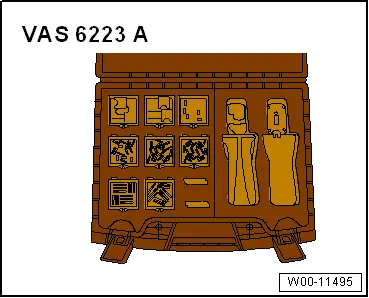
If disconnecting the connectors: Attach the Fiber-Optic Repair Set - Connector Protective Caps -VAS6223/9-.
When routing fiber optic cables, make sure not to go below the minimum bending radius of 25 mm. Do not crush or kink the fiber optic cables.
Repairing fiber optic cables. Refer to → Electrical Equipment; Rep. Gr.97; Fiber-Optic Cable.
General Information - Radio System, MMI Navigation Plus, I8H
I8H - MMI Radio high, MMI Navigation plus
Information Electronics Control Module 1 -J794- with integrated CD Player/DVD player/SD memory card reader/navigation system in the glove compartment
- Internal hard drive memory (HDD) for storing navigation data and MP3 files
- Front Information Display Control Head -J685-, display in center of the instrument panel
- Multimedia System Control Head -E380- in the center console, QW1
- DVD Changer -R161- in the luggage compartment on the left rear side, 6G2
- External Audio Source Connection -R199- in the center console storage compartment, UF7
- Digital Soand System Control Module -J525- in the luggage compartment
- Soand system: standard/BOSE/Bang & Olufsen, 8RM/9VD/9VS
- The Radio -R- is integrated in the Information Electronics Control Module 1 -J794-
Optional
- TV Tuner -R78- in the right rear of the luggage compartment, QU1/QV1
- Bluetooth interface, 9ZX
- Audi phone box, 9ZE
- Audi phone box connect, 9ZE/EL3
- Digital Radio -R147- integrated in the Information Electronics Control Module 1 -J794-, only Europe/Rest of World and QV3
- Radio System, Satellite - R146- integrated in the Information Electronics Control Module 1 - J794-, only USA and QV3
- Voice recognition system, QH1
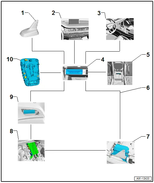
1 - Roof Antenna -R216-
2 - Front Information Display Control Head -J685- in center of the instrument panel
3 - Multimedia System Control Head -E380- in the center console
4 - Information Electronics Control Module 1 -J794- in the glove compartment
5 - Telephone Baseplate -R126-/External Audio Source Connection -R199- in the center console storage compartment
6 - MOST Bus
7 - Digital Soand System Control Module -J525- in the luggage compartment
8 - TV Tuner -R78- in luggage compartment on rear right side
9 - DVD Changer -R161- in the luggage compartment on the left rear side
10 - Left Front Microphone -R140-, Microphone Unit in Front Roof Module -R164- in the Front Interior Lamp -W1-
Fault Finding is performed using the "Guided Fault Finding" on the Vehicle Diagnostic Tester.
Notes on MOST Bus
The optical Data Bus "MOST Bus" is used in addition to the CAN Bus.
A fiber-optic cable is used. Fiber optic cables are routed inside corrugated tubes for protection.
Replace the complete fiber optic cable if possible.
The front surface of the connectors must not be contaminated.
If disconnecting the connectors: Attach the Fiber-Optic Repair Set - Connector Protective Caps -VAS6223/9-.
When routing fiber optic cables, make sure not to go below the minimum bending radius of 25 mm. Do not crush or kink the fiber optic cables.
Repairing fiber optic cables. Refer to → Electrical Equipment; Rep. Gr.97; Fiber-Optic Cable.

Component Location Overview - Radio
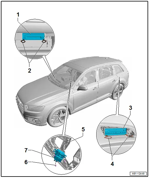
1 - Information Electronics Control Module 1 -J794-
- Connector Assignment. Refer to → Wiring diagrams, Troubleshooting & Component locations.
- Removing and Installing. Refer to → Chapter "Information Electronics Control Module 1 -J794-, Removing and Installing".
2 - Radio Removal Tool -T10057-
3 - DVD Changer -R161-
- Connector Assignment. Refer to → Wiring diagrams, Troubleshooting & Component locations.
- Removing and Installing. Refer to → Chapter "DVD Changer, Removing and Installing".
4 - Radio Removal Tool -T10057-
5 - Center Console Insert
6 - Bolt
- 3 Nm
- Quantity: 3
7 - Driver Volume Control -E67-
- Removing and Installing. Refer to → Chapter "Driver Volume Control -E67-, Removing and Installing".
Radio, Removing and Installing
The Radio -R- is integrated in the Information Electronics Control Module 1 -J794-. Refer to → Chapter "Information Electronics Control Module 1 -J794-, Removing and Installing".
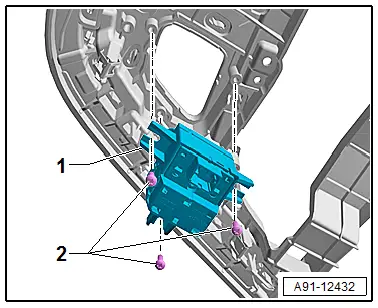
Driver Volume Control -E67-, Removing and Installing
The Driver Volume Control -E67- is installed in the center console insert.
- Turn off the ignition and all electrical equipment and remove the ignition key.
Removing
- Remove the center console insert. Refer to → Body Interior; Rep. Gr.68; Center Console; Center Console Insert, Removing and Installing.
The Driver Volume Control -E67- is attached to the center console insert.
- Remove the bolts -2- and then remove the Driver Volume Control -E67--1- from the center console insert.
Installing
- Install in reverse order of removal.
Tightening Specifications
- Refer to → Chapter "Component Location Overview - Radio"

