Audi Q7: Rear Expansion Valve, Removing and Installing
 Caution
This procedure contains mandatory replaceable parts. Refer to component overview prior to starting procedure.
Mandatory Replacement Parts
- O-ring - Rear Expansion Valve to Refrigerant Line - High Pressure Side
- O-ring - Refrigerant Line - Low Pressure Side to Rear Expansion Valve
 Note
Note
- After the A/C compressor is switched off in this vehicle, it may take a relatively long time for the pressure on the high pressure side to decrease (the expansion valve(s) is/are cold, the pressure on the low pressure side increases quickly after deactivation, the expansion valve(s) closes/close and the refrigerant can only flow slowly to the low pressure side).
- There are different versions of the expansion valve (and thus different refrigerant lines to the expansion valve) depending on the production period. Therefore, ensure proper allocation. Refer to the Parts Catalog.
Removing
- Turn off the ignition.
- Discharge the refrigerant circuit. Refer to → Refrigerant R134a Servicing; Rep. Gr.87; Refrigerant Circuit.
- Remove the heat shield for the transmission tunnel. Refer to → Body Exterior; Rep. Gr.66; Moldings, Trims, Extensions and Trim Panels; Floor Heat Shield, Removing and Installing.
- Remove the left underbody trim panel. Refer to → Body Exterior; Rep. Gr.66; Underbody Trim Panel; Underbody Trim Panels, Removing and Installing.
- Loosen the heat shield mat on the left center tunnel in the area of the transmission from the vehicle.
- Remove the refrigerant lines from the rear expansion valve. Refer to → Chapter "Refrigerant Lines from Rear Expansion Valve, Disconnecting and Connecting".
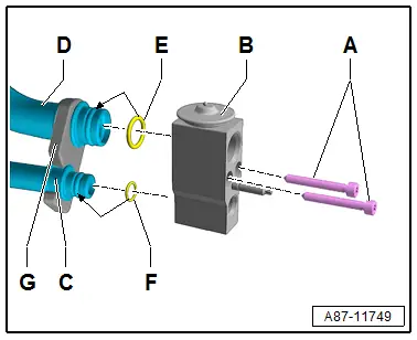
- Remove the bolts -A-.
- Remove the expansion valve -B- from refrigerant lines -C and D- (to the evaporator in the rear heater and A/C unit).
 Note
Note
Immediately seal off any open line connections and connection points with clean plugs, for example, taken from the Engine Bung Set -VAS6122-.
Installing
Install in reverse order of removal. Note the following:
- Clean refrigerant line connections on expansion valve -B- and on refrigerant lines -C and D-, and check for damage.
- Replace the O-ring seals -E and F-. Refer to the Parts Catalog for the correct version.
- Coat the O-rings -E and F- with refrigerant oil before installing. Refer to → Chapter "Refrigerant Circuit Seals".
- Ensure that the O-ring seals -E and F- are properly seated on the connections of refrigerant lines -C and D- to the evaporator.
- Ensure that the retaining plate -G- is seated properly on refrigerant lines -C and D-.
 Note
Note
The expansion valve is available in different versions (same housing but a different control characteristic). Refer to the Parts Catalog for the exact allocation.
- Place expansion valve -B- on the connections of refrigerant lines -C and D-.
- Insert and tighten bolts -A-.
- Tightening specification of bolts -A- (with a thread "M6") 9 Nm.
- Install the refrigerant lines to the rear expansion valve. Refer to → Chapter "Refrigerant Lines from Rear Expansion Valve, Disconnecting and Connecting".
- Check the routing of the refrigerant lines after attachment. They must be inserted in the provided brackets in a tension-free manner and must not come in contact with other components.
- Evacuate and charge the refrigerant circuit. Refer to → Refrigerant R134a Servicing; Rep. Gr.87; Refrigerant Circuit.
- Install the remaining removed components.
- Retrieve the Front A/C Display Control Head -E87- DTC memory and if necessary delete the displayed error. Refer to Vehicle Diagnostic Tester in the "Guided Fault Finding" function.
- Operate the A/C system after charging the refrigerant circuit. Refer to → Chapter "A/C System, Starting after Charging Refrigerant Circuit".
 Note
Note
- Note the information regarding operating the A/C system after filling. Refer to → Refrigerant R134a Servicing; Rep. Gr.87; A/C System, General Information.
- Check the functionality of the A/C system. Refer to Vehicle Diagnostic Tester in the "Guided Fault Finding" function.
Refrigerant Lines, Removing and Installing, from Rear Expansion Valve to Evaporator in Rear Heater and A/C Unit
Special tools and workshop equipment required
- Cleaning Solution -D 009 401 04-
 Caution
This procedure contains mandatory replaceable parts. Refer to component overview prior to starting procedure.
Mandatory Replacement Parts
- O-ring - Refrigerant Line - Low Pressure Side to Rear Expansion Valve
 Note
Note
To remove the evaporator and the rear heater and A/C unit, these refrigerant lines are not removed. Refer to → Chapter "Heater and A/C Unit, Removing and Installing, High A/C System".
Removing
- Remove the rear expansion valve. Refer to → Chapter "Rear Expansion Valve, Removing and Installing ".
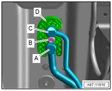
- Remove the nut -B-.
- Pry up the bracket -D- carefully from the center tunnel, at the same time loosen the bonding carefully.
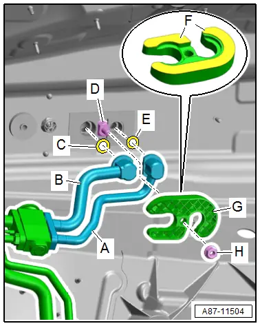
- Remove the refrigerant lines -A and C- from the refrigerant line connection to the evaporator in the rear heater and A/C unit.
Installing
Install in reverse order of removal. Note the following:
- Clean the adhesive surface on the body with Cleaning Solution -D 009 401 04-.
 Note
Note
Bracket -G- is bonded with double-sided adhesive tape on the floor plate of the center tunnel. As a result of this bonding, bracket remains in its position when removing the rear heater and A/C unit and the heat shield of the center tunnel does not need to be removed to install the rear heater and A/C unit.
- Clean the refrigerant line connection on the connection of the evaporator pipe -D- in the rear heater and A/C unit and on the refrigerant lines -A and B- and check them for damage.
- Replace the O-rings -C and E-. Refer to Parts Catalog for the version.
- Coat the O-ring seals lightly with refrigerant oil before installing. Refer to → Chapter "Refrigerant Circuit Seals".
- Ensure that the O-ring seals are seated properly on the connections of refrigerant lines -A and B-.
- Insert the refrigerant lines -A and B- in the connections of the evaporator -D-.
- Remove the protective film -F- carefully from the adhesive tapes.
- Install the bracket -G- on the center tunnel floor panel.
- Install and tighten hexagon nut -H-.
- Tightening specification of hexagon nut -H- with a thread "M8": 10 Nm.
- Remove the rear expansion valve. Refer to → Chapter "Rear Expansion Valve, Removing and Installing ".
- Check the routing of the refrigerant lines after attachment. They must be inserted in the provided brackets in a tension-free manner and must not come in contact with other components.
- Evacuate and charge the refrigerant circuit. Refer to → Refrigerant R134a Servicing; Rep. Gr.87; Refrigerant Circuit.
- Install the remaining removed components.
- Retrieve the Front A/C Display Control Head -E87- DTC memory and if necessary delete the displayed error. Refer to Vehicle Diagnostic Tester in the "Guided Fault Finding" function.
- Operate the A/C system after charging the refrigerant circuit. Refer to → Chapter "A/C System, Starting after Charging Refrigerant Circuit".
 Note
Note
- Note the information regarding operating the A/C system after filling. Refer to → Refrigerant R134a Servicing; Rep. Gr.87; A/C System, General Information.
- Check the functionality of the A/C system. Refer to Vehicle Diagnostic Tester in the "Guided Fault Finding" function.
Refrigerant Lines, Removing and Installing, from Connection Point to Rear Expansion Valve
 Caution
This procedure contains mandatory replaceable parts. Refer to component overview prior to starting procedure.
Mandatory Replacement Parts
- O-ring - Pass-Through for the Refrigerant Lines in the Vehicle Interior to Refrigerant Line - Low Pressure Side
- O-ring - Rear Expansion Valve to Refrigerant Line - High Pressure Side
- O-ring - Rear Expansion Valve to Refrigerant Line - Low Pressure Side
Removing
- Remove the refrigerant lines from the rear expansion valve. Refer to → Chapter "Refrigerant Lines from Rear Expansion Valve, Disconnecting and Connecting".
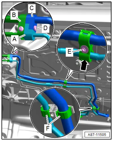
- Remove the nut -E-, release the catch -arrow- and open the bracket.
- Release the retainers and open the cable holder -F-.
- Remove the bolt -D-.
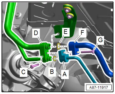
- Remove the refrigerant lines to the rear expansion valve -A and C- from the refrigerant lines -B- and to the front heater and A/C unit.
Installing
Install in reverse order of removal. Note the following:
- Clean the refrigerant lines connections on the connection from the refrigerant pipes -C- and on the refrigerant lines -A and E- for damage.
- Replace the O-ring seals -B and D- on the refrigerant line connections -A and E-. Refer to the Parts Catalog for the correct version.
- Coat the O-ring seals lightly with refrigerant oil before installing. Refer to → Chapter "Refrigerant Circuit Seals".
- Ensure that the O-ring seals are seated properly on the connection of refrigerant line -C-.
- Insert the refrigerant lines -A and E- in the refrigerant line connection -C-.
- Insert and tighten the bolt -F-.
- Bolt tightening specification -F- 9 Nm
- Check the routing of the refrigerant lines after attachment. They must be inserted in the provided brackets in a tension-free manner and must not come in contact with other components.
- Evacuate and charge the refrigerant circuit. Refer to → Refrigerant R134a Servicing; Rep. Gr.87; Refrigerant Circuit.
- Install the remaining removed components.
- Retrieve the Front A/C Display Control Head -E87- DTC memory and if necessary delete the displayed error. Refer to Vehicle Diagnostic Tester in the "Guided Fault Finding" function.
- Operate the A/C system after charging the refrigerant circuit. Refer to → Chapter "A/C System, Starting after Charging Refrigerant Circuit".
 Note
Note
Note the information regarding operating the A/C system after filling. Refer to → Refrigerant R134a Servicing; Rep. Gr.87; A/C System, General Information.

