Audi Q7: Condenser, Removing and Installing
Refrigerant Lines, Disconnecting and Connecting at Condenser
Special tools and workshop equipment required
- Elbow Assembly Tool -T10118-
 Caution
This procedure contains mandatory replaceable parts. Refer to component overview prior to starting procedure.
Mandatory Replacement Parts
- O-ring - Plug with Filter Element to Dryer Bag
 Note
Note
Condenser is available in different versions, depending on version of vehicle. Refer to the Parts Catalog.
Removing
- Turn off the ignition.
- Discharge the refrigerant circuit. Refer to → Refrigerant R134a Servicing; Rep. Gr.87; Refrigerant Circuit.
- Remove the front noise insulation. Refer to → Body Exterior; Rep. Gr.66; Noise Insulation; Noise Insulation, Removing and Installing.
- Vehicles with left charge air cooler: remove the end panel for the front bumper cover. Refer to → Body Exterior; Rep. Gr.63; Front Bumper; Attachments, Removing and Installing.
- Remove the left air intake grille. Refer to → Body Exterior; Rep. Gr.63; Front Bumper; Attachments, Removing and Installing.
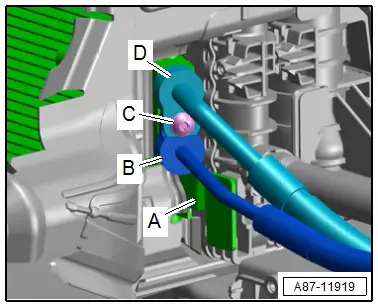
- Remove the bolt -C-.
- Remove the refrigerant lines -B and D- from the condenser -A-.
- Close open line connections and condenser connections.
 Note
Note
Immediately seal off any open line connections and connection points with clean plugs, for example, taken from the Engine Bung Set -VAS6122-.
Installing
Installation is done is reverse order, observe the following:
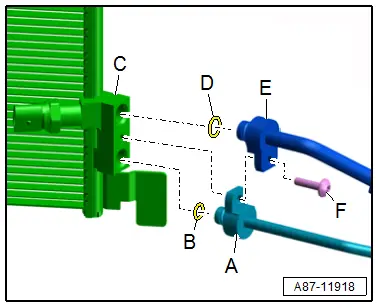
- Clean the refrigerant line connections on the condenser -C- and on the refrigerant lines -A and E- and check for damage.
- Replace the O-rings seals -D-. Refer to the Parts Catalog for the version.
- Check the alignment pin (installed in the condenser connection or the refrigerant line, not present in all connections) for damage and proper seating.
 Note
Note
- Follow the instructions for installing the O-rings. Refer to → Chapter "Refrigerant Circuit Seals".
- Following attachment, check routing of refrigerant lines on condenser. They must be inserted in brackets provided and not make contact with other components.
- Coat O-ring seals -J and K- lightly with refrigerant oil before installation. Refer to → Chapter "Refrigerant Circuit Seals".
- Pay attention that the O-ring seals are seated correctly on the refrigerant lines -A and E-.
- Insert the refrigerant lines -A and E- in the connections on the condenser.
- Insert and tighten the bolt -F-.
- Tightening specification of bolt -F- with a thread "M6" 9 Nm.
- Check the routing of the refrigerant lines after attachment. They must be inserted in the provided brackets in a tension-free manner and must not come in contact with other components.
- Evacuate and charge the refrigerant circuit. Refer to → Refrigerant R134a Servicing; Rep. Gr.87; Refrigerant Circuit.
- Install the remaining removed components.
- Retrieve the Front A/C Display Control Head -E87- DTC memory and if necessary delete the displayed error using. Refer to Vehicle Diagnostic Tester in the "Guided Fault Finding" function.
- Operate the A/C system after charging the refrigerant circuit. Refer to → Chapter "A/C System, Starting after Charging Refrigerant Circuit".
 Note
Note
Note the information regarding operating the A/C system after filling. Refer to → Refrigerant R134a Servicing; Rep. Gr.87; A/C System, General Information.
Condenser, Removing and Installing
 Note
Note
- The radiator and condenser may have small indentations on the fins even when installed correctly. It is not damage. Do not replace the radiator or condenser because of those small indentations.
- Slight deformations on the side securing straps on the condenser (for example, due to an accident), can result in an unparallel flow from the condenser and radiator; this can be resolved by pulling the straps back as long as the function/condenser sealing is not impaired. The straps on the condenser do not need to be replaced if there are small deformations.
- A slight bending of the condenser (up to 4 mm) is permissible as long as there is sufficient distance (minimum 4 mm) between the condenser and the radiator and the function/sealing of the condenser (of the refrigerant circuit) is not impaired. The condenser does not have to be replaced if there are slight deformations.
- Condenser is available in different versions, depending on version of vehicle. Refer to the Parts Catalog.
Removing
- Turn off the ignition.
- Discharge the refrigerant circuit. Refer to → Refrigerant R134a Servicing; Rep. Gr.87; Refrigerant Circuit.
- Remove the lock carrier cover. Refer to → Body Exterior; Rep. Gr.63; Front Bumper; Attachments, Removing and Installing.
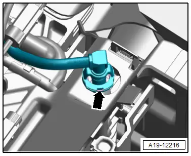
- Gasoline engine: pry up the clamp -arrow- and remove the coolant line from the charge air cooling circuit cooler.
 Note
Note
Immediately seal off any open line connections and connection points with clean plugs, for example, taken from the Engine Bung Set -VAS6122-.
- Remove the bolts -2- and the move the bracket -1- with the cable toward the rear.
- Release the left and right catches -4- and remove the upper air duct -3-.
- Disconnect the refrigerant lines from the condenser. Refer to → Chapter "Refrigerant Lines, Disconnecting and Connecting at Condenser".
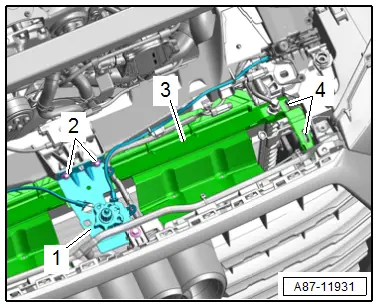
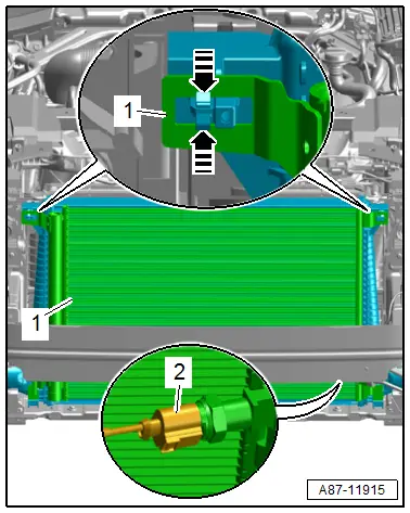
- Disconnect the connector -2- for the High Pressure Sensor -G65-.
- Release the catches in direction of -arrows- and remove the condenser -1- slightly from the radiator, at the same time push the left and right air ducts to the side if necessary.
- Remove the condenser upward from the mount on the radiator.
Installing
Installation is done is reverse order, observe the following:
 Note
Note
The removed condenser contains refrigerant oil that must be returned to the refrigerant circuit (with the new condenser). Refer to → Refrigerant R134a Servicing; Rep. Gr.87; Refrigerant Circuit Components, Replacing.
- Install the refrigerant lines on the condenser. Refer to → Chapter "Refrigerant Lines, Disconnecting and Connecting at Condenser".
- Evacuate and charge the refrigerant circuit. Refer to → Refrigerant R134a Servicing; Rep. Gr.87; Refrigerant Circuit.
- Install the remaining removed components.
- Retrieve the Front A/C Display Control Head -E87- DTC memory and if necessary delete the displayed error using. Refer to Vehicle Diagnostic Tester in the "Guided Fault Finding" function.
- Operate the A/C system after charging the refrigerant circuit. Refer to → Chapter "A/C System, Starting after Charging Refrigerant Circuit".
 Note
Note
Note the information regarding operating the A/C system after filling. Refer to → Refrigerant R134a Servicing; Rep. Gr.87; A/C System, General Information.