Audi Q7: Dryer Bag/Dryer Cartridge, Removing and Installing
Dryer Cartridge, Removing and Installing, from Receiver/Dryer on Condenser
 Caution
This procedure contains mandatory replaceable parts. Refer to component overview prior to starting procedure.
Mandatory Replacement Parts
- O-ring - Plug with Filter Element to Dryer Bag
 Note
Note
There are different condenser versions as well as the dryer cartridge installed inside them. Pay attention to the correct allocation. Refer to the Parts Catalog.
Removing
- Remove the condenser. Refer to → Chapter "Condenser, Removing and Installing".
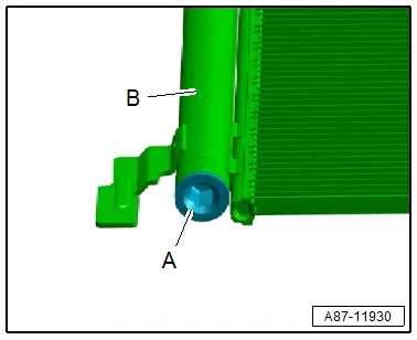
- Remove the plug -A-.
- Remove the dryer bag from the condenser -B-.
- Seal the open the connection on receiver/dryer of the condenser with plug -A- (to prevent dirt and moisture from getting in).
 Note
Note
Immediately seal off any open line connections and connection points with clean plugs, for example, taken from the Engine Bung Set -VAS6122-.
Installing
 Note
Note
There are different condenser versions as well as the dryer bag installed inside them. Pay attention to the correct allocation. Refer to the Parts Catalog.
Installation is done is reverse order, observe the following:
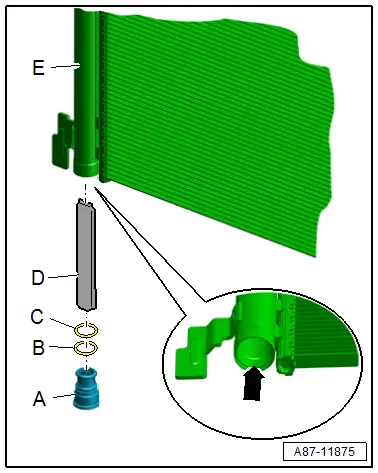
- Check the receiver/dryer -E- and the threads on the condenser via the opening for debris and damage -arrow-.
- Replace the plug -A- with the filter element and both O-ring seals -B and C- (included in the delivery of the dryer). Refer to the Parts Catalog.
- Coat the O-ring seals -B and C- lightly with refrigerant oil prior to installation. Refer to → Chapter "Refrigerant Circuit Seals".
- Check the O-ring seals for proper seating in grooves of the respective components.
- Keep the dryer bag -D- sealed in its air-tight package as long as possible. Open the package just before installing the dryer cartridge in the receiver/dryer of the condenser. The dryer cartridge absorbs moisture from the surrounding air in a very short time and becomes unusable.
- Remove the dryer bag -D- from its package and insert in the receiver/dryer.
- Install the plug -A- and the O-ring seals -B and C-.
- Evacuate and charge the refrigerant circuit. Refer to → Refrigerant R134a Servicing; Rep. Gr.87; Refrigerant Circuit.
- Install the remaining removed components.
- Retrieve the Front A/C Display Control Head -E87- DTC memory and if necessary delete the displayed error. Refer to Vehicle Diagnostic Tester in the "Guided Fault Finding" function.
- Operate the A/C system after charging the refrigerant circuit. Refer to → Chapter "A/C System, Starting after Charging Refrigerant Circuit".
 Note
Note
Note the information regarding operating the A/C system after filling. Refer to → Refrigerant R134a Servicing; Rep. Gr.87; A/C System, General Information.
Evacuating and Charging Valve, Removing and Installing, Low and High Pressure Side
 WARNING
Danger due to refrigerant coming out under pressure.
Danger of frost bite to skin and other parts of the body.
- Evacuate the refrigerant and immediately open the refrigerant circuit afterward.
- If more than 10 minutes have elapsed since evacuating the refrigerant and the refrigerant circuit was not opened, evacuate the refrigerant again. Pressure in the refrigerant circuit is caused by evaporation.
 Note
Note
- Certain tools are required to discharge the refrigerant circuit, these work procedures must only be performed by trained personnel as well. Refer to Refrigerant R134a Servicing.
- Depending on the vehicle version installed in the left plenum chamber (near the brake fluid reservoir, as shown here) under the plenum chamber or in the left engine compartment
Special tools and workshop equipment required
- Refrigerant Sockets -T10364-
Removing
- Remove the plenum chamber cover. Refer to → Body Exterior; Rep. Gr.50; Bulkhead; Plenum Chamber Cover, Removing and Installing.
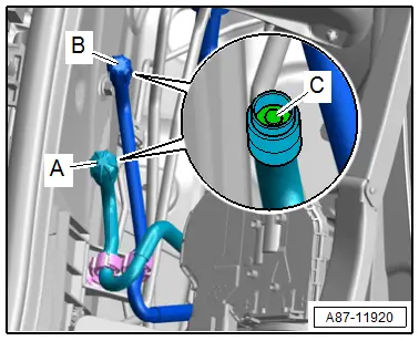
- Remove the closure caps (with seal) -A or B-.
- Discharge the refrigerant circuit. Refer to → Refrigerant R134a Servicing; Rep. Gr.87; Refrigerant Circuit.
- Remove the service connection -C- using the Refrigerant Sockets -T10364- and a suitable adapter.
 Note
Note
Additional information regarding the service connection. Refer to → Refrigerant R134a Servicing; Rep. Gr.87; A/C System, General Information.
Installing
Install in reverse order of removal. Note the following:
- Evacuate and charge the refrigerant circuit. Refer to → Refrigerant R134a Servicing; Rep. Gr.87; Refrigerant Circuit.
- Operate the A/C system after charging the refrigerant circuit. Refer to → Chapter "A/C System, Starting after Charging Refrigerant Circuit".
- Install the plenum chamber cover. Refer to → Body Exterior; Rep. Gr.50; Bulkhead; Plenum Chamber Cover, Removing and Installing.
- Check the DTC memory and erase any displayed entries using. Refer to Vehicle Diagnostic Tester in the "Guided Fault Finding" function.
A/C System, Starting after Charging Refrigerant Circuit
 Note
Note
- Only start the engine after refrigerant circuit has been assembled.
- If possible start the engine only with a filled refrigerant circuit.
- Do not start the engine while evacuating the refrigerant circuit or when the circuit is already evacuated (the A/C compressor could be damaged). Refer to → A/C System with Refrigerant R134a; Rep. Gr.87; A/C System, General Information.
- The A/C compressor on the version without a A/C Clutch -N25- is always driven by the belt pulley. To prevent damage when the compressor is idling, it is lubricated by an "Internal oil circuit".
- The A/C compressor has an "internal oil circuit" to ensure that the A/C compressor is not damaged when the refrigerant circuit is empty. The prerequisite for the internal lubrication is a residual amount of refrigerant oil in the A/C compressor and there is no vacuum in the refrigerant circuit.
- The engine may only be started when the refrigerant circuit is installed correctly. For example; if the refrigerant lines are not connected to A/C compressor, when the engine is running the A/C compressor may heat up (via internal heat generation) so much that the A/C compressor will be damaged.
- A/C Compressor Regulator Valve -N280- is not activated when the refrigerant circuit is empty and the A/C compressor idles with the engine. Since there is no refrigerant in the circuit, the required refrigerant oil for lubricating the A/C compressor is not supplied.
- Note the information regarding operating the A/C system after filling. Refer to → Refrigerant R134a Servicing; Rep. Gr.87; A/C System, General Information.
- All removed parts are reinstalled.
- The refrigerant circuit is filled → Refrigerant R134a Servicing; Rep. Gr.87; A/C System, General Information.
If it is necessary to start the engine with a discharged refrigerant circuit:
- Refrigerant circuit must be fully assembled.
- There must be no vacuum in the refrigerant circuit.
- At least a quarter of the prescribed refrigerant oil must be in the A/C compressor.
- Do not let the engine speed go above 2,500 RPM.
- The engine should only run as long as is absolutely necessary.
Note the following when starting engine for the first time after filling refrigerant circuit:
- Turn on the ignition.
- Adjust the "OFF" mode on the Front A/C Display Control Head -E87- (and on a vehicle with a "High" A/C system on the Rear A/C Display Control Head -E265-) the indicator lamp in the A/C and the A/C MAX button of the Front A/C Display Control Head -E87- does not turn on. The A/C system and the activation of the A/C compressor are switched off by the A/C Compressor Regulator Valve -N280-.
- Start the engine with the A/C compressor switched off ("OFF" mode set) and let the engine idle for at least five minutes (with the A/C compressor off).
- Open all instrument panel vents and the vents in the center console and in the B-pillars.
- Turn on the A/C system and the A/C compressor activation by pressing the Auto button on the Front A/C Display Control Head -E87- ("Auto" mode selected and indicator lamps in the AUTO buttons and the A/C MAX button for the Front A/C Display Control Head -E87- illuminate).
- If possible select on the Front A/C Display Control Head -E87- the SYNC and Rear functions.
 Note
Note
- By selecting the SYNC function, the settings for the front driver side are applied to the front passenger side and also on the Rear A/C Display Control Head -E265-.
- If the indicator lamp in the A/C MAX button of the Front A/C Display Control Head -E87- does not turn on, press the A/C MAX button of the Front A/C Display Control Head -E87-.
- Check the indicator lamps in the AUTO buttons on the Front A/C Display Control Head -E87- (and the Rear A/C Display Control Head -E265- if present). If they do not illuminate, press the AUTO buttons.
- Set the temperature preselection for the driver side on the Front A/C Display Control Head -E87- to "cold".
 Note
Note
via the previous selection of the SYNC and Rear function, the settings for the front driver side are applied to the front passenger side and also on the Rear A/C Display Control Head -E265-.
- Check the temperature preselection for the front passenger side on the Front A/C Display Control Head -E87- (and also on the Rear A/C Display Control Head -E265- if present) and set it to "cold" if necessary.
- Allow the engine to idle for at least five minutes with the A/C compressor switched on.
 Note
Note
After the A/C compressor is started as described, the cooling output of the A/C system can now be checked if necessary. Refer to → Chapter "Cooling Output, Checking".
