Audi Q7: Overview - Air Routing and Air Distribution in Passenger Compartment, Front
 Note
Note
Depending on vehicle equipment, there are different versions of the A/C system for the Audi Q7. Make sure to use the correct version and pay attention to the allocation of different components. Refer to → Chapter "A/C System Versions" and Parts Catalog.
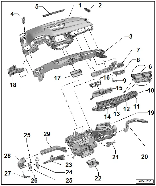
1 - Instrument Panel
- With air guides to the defroster vents and various instrument panel vents
- There are different versions. Refer to the Parts Catalog.
- Removing and installing. Refer to → Body Interior; Rep. Gr.70; Instrument Panel; Instrument Panel, Removing and Installing.
2 - Vent to Right Front Door (Front Passenger Doors)
- Removing and installing. Refer to → Body Interior; Rep. Gr.70; Instrument Panel; Overview - Instrument Panel.
3 - Air Guide / Instrument Panel
- With the air ducts to the defroster vents and various instrument panel vents to the windshield and the side window.
- There are different versions. Refer to the Parts Catalog.
- The air guide is a component of the instrument panel -item 1- and cannot be replaced separately. Refer to → Body Interior; Rep. Gr.70; Instrument Panel; Instrument Panel, Removing and Installing.
4 - Vent to Left Front Door (Driver Side Doors)
- Removing and installing. Refer to → Body Interior; Rep. Gr.70; Instrument Panel; Overview - Instrument Panel.
5 - Defroster Vent/Windshield
- Air guide to windshield
- Removing and installing. Refer to → Body Interior; Rep. Gr.70; Instrument Panel; Overview - Instrument Panel.
- If the intermediate piece for air routing/defrost -item 17- was crushed or crumpled when the instrument panel was installed, the air routed to the windshield will be uneven or insufficient.
6 - Closure Caps
- On vehicles with a "Low" or "Mid" A/C system the vent for the broadband nozzle does not function. The vent is closed from behind with a closure cap.
7 - Air Duct to Right Instrument Panel Vent and the Broadband Nozzle
- There are different versions. Refer to the Parts Catalog.
- This air duct is installed on vehicles with a "Mix" or "High" A/C system
Removing and installing:
- Remove the glove compartment. Refer to → Body Interior; Rep. Gr.68; Storage Compartments and Covers; Glove Compartment, Removing and Installing.
- Remove the right instrument panel vent trim -item 10-. Refer to → Body Interior; Rep. Gr.70; Instrument Panel; Overview - Instrument Panel.
- Remove the expanding rivet and the bolt.
- Disconnect the connector on the Right Front Upper Body Vent Temperature Sensor -G386- and if necessary on the Instrument Panel Vent Motor -V562- and remove the air duct.
 Note
Note
Before installing check for damage, even the smallest damage on the components can lead to complaints (for example due to noises).
8 - Air Duct to the Right Instrument Panel Vent
- There are different versions. Refer to the Parts Catalog.
- This air duct is installed on vehicles with a "Low" or "Mid" A/C system
Removing and installing:
- Remove the glove compartment. Refer to → Body Interior; Rep. Gr.68; Storage Compartments and Covers; Glove Compartment, Removing and Installing.
- Remove the right instrument panel vent trim -item 10-. Refer to → Body Interior; Rep. Gr.70; Instrument Panel; Overview - Instrument Panel.
- Remove the air duct.
 Note
Note
Before installing check for damage, even the smallest damage on the components can lead to complaints (for example due to noises).
9 - Right Front Upper Body Vent Temperature Sensor -G386-
- Refer to → Chapter "Right Front Upper Body Vent Temperature Sensor -G386-, Removing and Installing"
- Check the Right Front Upper Body Vent Temperature Sensor -G386-. Refer to Vehicle Diagnostic Tester in the "Guided Fault Finding" function
10 - Front Passenger Side Instrument Panel Vent
- There are different versions. Refer to the Parts Catalog.
- Removing and installing. Refer to → Body Interior; Rep. Gr.70; Instrument Panel; Overview - Instrument Panel.
11 - Right Instrument Panel Vent
- There are different versions. Refer to the Parts Catalog.
- with Position Sensor in Right Side Vent -G629- (vehicles with a "Low" or "Mid" A/C system)
- with Position Sensor in Right Side Vent -G629- and Instrument Panel Vent Button -E815- (vehicles with a "Mix" or "High" A/C system)
- Removing and installing. Refer to → Body Interior; Rep. Gr.70; Instrument Panel; Overview - Instrument Panel.
- Check the Position Sensor in Right Side Vent -G629- (and Instrument Panel Vent Button - E815-). Refer to Vehicle Diagnostic Tester in the "Guided Fault Finding" function.
 Note
Note
After replacement of the potentiometer (for adapting the end stops), adapt the Front A/C Display Control Head -E87-. Refer to Vehicle Diagnostic Tester in the "Guided Fault Finding" function.
12 - Broadband Nozzle Vent
- Removing and installing. Refer to → Body Interior; Rep. Gr.70; Instrument Panel; Overview - Instrument Panel.
 Note
Note
- The instrument panel vent can only be removed and installed with the trim for the right instrument panel vent removed -item 10-.
- Does not have a function on vehicles with a "Low" or "Mid" A/C system. The vent is closed from behind with a closure cap -item 6-.
13 - Right Center Instrument Panel Vent
- Removing and installing. Refer to → Body Interior; Rep. Gr.70; Instrument Panel; Overview - Instrument Panel.
 Note
Note
The instrument panel vent can only be removed and installed with the trim for the right instrument panel vent removed -item 10-.
14 - Left Center Instrument Panel Vent
- Removing and installing. Refer to → Body Interior; Rep. Gr.70; Instrument Panel; Overview - Instrument Panel.
 Note
Note
The instrument panel vent can only be removed and installed with the trim for the right instrument panel vent removed -item 10-.
15 - Air Duct to Center Instrument Panel Vents
Removing and installing:
- Remove the right instrument panel vent -item 10-. Refer to → Body Interior; Rep. Gr.70; Instrument Panel; Overview - Instrument Panel.
- Remove the left and right expanding rivet and the air duct.
16 - Adapter for the Air Duct to the Center Instrument Panel Vents
Removing and installing:
- Remove the right instrument panel vent -item 10 -. Refer to → Body Interior; Rep. Gr.70; Instrument Panel; Overview - Instrument Panel.
- Remove the air duct to center instrument panel vents -item 15-.
- Loosen the left and right catches and remove the air duct from the heater and A/C unit.
17 - Air Duct/Defrost Intermediate Piece
- There are different versions. Refer to the Parts Catalog.
- Removing and installing. Refer to → Body Interior; Rep. Gr.70; Instrument Panel; Overview - Instrument Panel.
 Note
Note
- If the intermediate piece air flow / defrost (and) was crushed or crumpled when the dash panel was being installed, then the air flow to the windshield will be uneven or insufficient.
- Before installing check for damage, even the smallest damage on the components can lead to complaints (for example due to noises).
18 - Left Instrument Panel Vent
- Versions with Position Sensor in Left Side Vent -G628- and Driver Side Ionizer Button -E830-
- Instrument panel vent, removing and installing. Refer to → Body Interior; Rep. Gr.70; Instrument Panel; Overview - Instrument Panel.
- Check the position sensor in Left Side Vent -G628-. Refer to Vehicle Diagnostic Tester in the "Guided Fault Finding" function
 Note
Note
- After replacement of the potentiometer (for adapting the end stops), adapt the Front A/C Display Control Head -E87-. Refer to Vehicle Diagnostic Tester in the "Guided Fault Finding" function.
- The driver side air ionization is only intended for certain vehicles with a "Mix" or "High" Air ionization and only for certain market specific vehicles. Refer to the Audi Sales Program.
- The Driver Side Ionizer Button -E830- and the Driver Side Ionizer -J1105- is always installed in the driver side air duct.
19 - Front Heater and A/C Unit
- Different versions. Refer to → Chapter "Overview - Heater and A/C Unit" and the Parts Catalog.
- Refer to → Chapter "Heater and A/C Unit, Removing and Installing"
- Air intake, air vents and air routing in the heater and A/C unit. Refer to → Chapter "Air Duct in Front Heater and A/C unit ".
20 - Right Air Duct Channel
Removing and installing:
- Remove the instrument panel. Refer to → Body Interior; Rep. Gr.70; Instrument Panel; Instrument Panel, Removing and Installing.
- Remove the bolt on the heater and A/C unit air intake housing.
- Remove the air duct.
 Note
Note
- If the air duct was crushed or crumpled when the instrument panel was being installed, then the air flow will be uneven or insufficient.
- Before installing check for damage, even the smallest damage on the components can lead to complaints (for example due to noises).
21 - Right Front Footwell Vent
- Refer to → Chapter "Front Passenger Side Footwell Vent, Removing and Installing"
22 - Air Duct
- Different versions with a "Low", "Mid", "Mix" or "High" A/C system. Refer to the Parts Catalog.
- This air duct is installed on vehicles with a "Mid", "Mix" or "High" A/C system.
Removing and installing:
- Remove the center console. Refer to → Body Interior; Rep. Gr.68; Center Console; Center Console, Removing and Installing.
- Remove the rear air duct channel. Refer to → Chapter "Air Ducts and Vents in the Rear Vehicle Interior, Low A/C System".
- Remove the air duct.
 Note
Note
Before installing check for damage, even the smallest damage on the components can lead to complaints (for example due to noises).
- From the front heater and A/C unit to the rear heater and A/C unit/ to the rear air duct or to the center console lower air duct
- Removing and installing. Refer to → Chapter "Heater and A/C Unit, Removing and Installing, Mid or Mix A/C System" or → Chapter "Heater and A/C Unit, Removing and Installing, High A/C System".
23 - Left Front Footwell Vent
- Refer to → Chapter "Driver Side Footwell Vent, Removing and Installing".
24 - Driver Side Ionizer -J1105-
- Not intended for all vehicles, only installed on specific vehicles with a "Mix" or "High" A/C system. Refer to → Wiring diagrams, Troubleshooting & Component locations.
- Check. Refer to Vehicle Diagnostic Tester in the "Guided Fault Finding" function
- Refer to → Chapter "Driver Side Ionizer -J1105-, Removing and Installing"
25 - Bolt
- 1 Nm
26 - Driver Side Ionizer -J1105- Bracket
- Removing and installing. Refer to → Chapter "Driver Side Ionizer -J1105-, Removing and Installing".
27 - Left Front Upper Body Vent Temperature Sensor -G385-
- To check. Refer to Vehicle Diagnostic Tester in the "Guided Fault Finding" function
- Refer to → Chapter "Left Front Upper Body Vent Temperature Sensor -G385-, Removing and Installing".
28 - Air Duct to the Left Instrument Panel Vent
- Different versions of the vehicles with or without the Driver Side Ionizer -J1105-. Refer to the Parts Catalog.
Removing and installing
- Remove the driver side instrument panel cover. Refer to → Body Interior; Rep. Gr.68; Storage Compartments and Covers; Driver Side Instrument Panel Cover, Removing and Installing.
- Remove the left instrument panel vent -item 18-. Refer to → Body Interior; Rep. Gr.70; Instrument Panel; Overview - Instrument Panel.
- Remove the expanding rivet.
- Disconnect the connector on the Left Front Upper Body Vent Temperature Sensor - G385- and if necessary on the Driver Side Ionizer -J1105- and remove the air duct.
 Note
Note
Before installing check for damage, even the smallest damage on the components can lead to complaints (for example due to noises).
29 - Left Air Duct
Removing and installing:
- Remove the instrument panel. Refer to → Body Interior; Rep. Gr.70; Instrument Panel; Instrument Panel, Removing and Installing.
- Remove the air duct.
 Note
Note
- Do not remove the instrument panel crossmember, to remove the instrument panel crossmember depending on the vehicle version the windshield must be removed. Refer to → Body Interior; Rep. Gr.70; Instrument Panel; Instrument Panel, Removing and Installing.
- If the air duct was crushed or crumpled when the instrument panel was being installed, then the air flow will be uneven or insufficient.
- Before installing check for damage, even the smallest damage on the components can lead to complaints (for example due to noises).

