Audi Q7: Rear Seat Entertainment System (RSE)
Overview - Rear Seat Entertainment System
The Rear Seat Entertainment System (RSE) consists of:
- Left Rear Information Display Control Head Control Module -J648-/Right Rear Information Display Control Head Control Module -J649- on the left/right front seat backrest frame
- Information Electronics Control Module 1 -J794- in the glove compartment
- Multimedia Display Unit 3 Bracket -R315-/Multimedia Display Unit 4 Bracket -R316- on the left/right front seat backrest
- Multimedia Display Unit 3 -Y31-/Multimedia Display Unit 4 -Y32- on the Multimedia Display Unit 3 Bracket -R315-/ Multimedia Display Unit 4 Bracket -R316-
Component Location Overview - Rear Seat Entertainment System
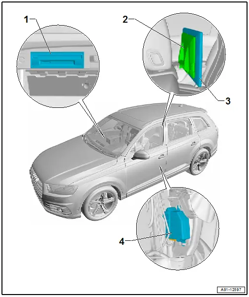
1 - Information Electronics Control Module 1 -J794-
- In the glove compartment
- Connector Assignment. Refer to → Wiring diagrams, Troubleshooting & Component locations.
- Removing and Installing. Refer to → Chapter "Information Electronics Control Module 1 -J794-, Removing and Installing".
2 - Multimedia Display Unit 3 Bracket -R315-/ Multimedia Display Unit 4 Bracket -R316-
- On the left/right front seat backrest
- Removing and Installing. Refer to → Chapter "Multimedia Display Unit 3 Bracket -R315-/ Multimedia Display Unit 4 Bracket -R316-, Removing and Installing".
3 - Multimedia Display Unit 3 -Y31-/ Multimedia Display Unit 4 -Y32-
- On the Multimedia Display Unit 3 Bracket -R315-/ Multimedia Display Unit 4 Bracket -R316-
- Removing and Installing. Refer to → Chapter "Multimedia Display Unit 3 -Y31-/ Multimedia Display Unit 4 -Y32-, Removing and Installing".
4 - Left Rear Information Display Control Head Control Module -J648-/ Right Rear Information Display Control Head Control Module -J649-
- On the right/left front seat backrest frame
- Connector Assignment. Refer to → Wiring diagrams, Troubleshooting & Component locations.
- Removing and Installing. Refer to → Chapter "Left and Right Rear Information Display Control Head Control Module -J648-/-J649-, Removing and Installing".
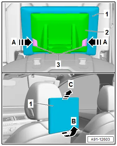
Multimedia Display Unit 3 -Y31-/ Multimedia Display Unit 4 -Y32-, Removing and Installing
The Multimedia Display Unit 3 - Y31-/ Multimedia Display Unit 4 - Y32- is installed on the Multimedia Display Unit 3 Bracket - R315-/ Multimedia Display Unit 4 Bracket - R316- on the top of the left/right front seat backrest.
 Note
Note
The removal and installation is described for the left side. Removing and installing on the right side is identical.
Removing
- Turn off the ignition and all electrical equipment and remove the ignition key.
- Release the catches -3- on the Multimedia Display Unit 4 Bracket - R316--2- in the direction of the arrow -A-.
- Remove the Multimedia Display Unit 4 -Y32--1- at the same time in the direction of the arrow -B- from the Multimedia Display Unit 4 Bracket -R316--2-.
- Remove the Multimedia Display Unit 4 -Y32--1- in the direction of the arrow -C- from the Multimedia Display Unit 4 Bracket -R316--2-.
Installing
- Install in reverse order of removal. Note the following:
- Install the Multimedia Display Unit 4 -Y32- until it engages audibly in the Multimedia Display Unit 4 Bracket -R316-.
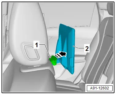
Multimedia Display Unit 3 Bracket -R315-/ Multimedia Display Unit 4 Bracket -R316-, Removing and Installing
The Multimedia Display Unit 3 Bracket -R315-/ Multimedia Display Unit 4 Bracket - R316- is installed at the top on the right/left front seat backrest.
 Note
Note
The removal and installation is described for the left side. Removing and installing on the right side is identical.
Removing
- Turn off the ignition and all electrical equipment and remove the ignition key.
- Remove the Multimedia Display Unit 4 -Y32-. Refer to → Chapter "Multimedia Display Unit 3 -Y31-/ Multimedia Display Unit 4 -Y32-, Removing and Installing".
- Release the catch -1- on the Multimedia Display Unit 4 Bracket - R316--2- in the direction of the -arrow-.
- Remove the Multimedia Display Unit 4 Bracket - R316--2- toward the rear from the left front seat backrest.
Installing
- Install in reverse order of removal. Note the following:
- Push in the Multimedia Display Unit 4 Bracket -R316- until it engages audibly in the left front seat backrest.
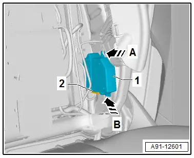
Left and Right Rear Information Display Control Head Control Module -J648-/-J649-, Removing and Installing
The Left and Right Rear Information Display Control Head Control Module -J648-/-J649- is installed on the inside of the right/left front seat backrest frame.
 Note
Note
The removal and installation is described for the left side. Removing and installing on the right side is identical.
Removing
- Turn off the ignition and all electrical equipment and remove the ignition key.
- Remove the cover and cushion. Refer to → Body Interior; Rep. Gr.74; Front Seat Covers and Cushions; Backrest Cover and Cushion, Removing and Installing.
- Push the Left Rear Information Display Control Head Control Module - J648--1- carefully in the direction of the arrow -A- from the upper eye on the backrest frame.
- Push the Left Rear Information Display Control Head Control Module - J648--1- in the direction of the arrow -B- from the lower eye on the backrest frame.
- Engage the connector -2- on the Left Rear Information Display Control Head Control Module -J648--1- and disconnect.
- Unclip the wires from the Left Rear Information Display Control Head Control Module -J648--1-.
- Remove the Left Rear Information Display Control Head Control Module -J648--1-.
Installing
- Install in reverse order of removal.

